Notice. New forum software under development. It's going to miss a few functions and look a bit ugly for a while, but I'm working on it full time now as the old forum was too unstable. Couple days, all good. If you notice any issues, please contact me.
Mixtel90 Guru Joined: 05/10/2019 Location: United KingdomPosts: 9220
Posted: 09:14am 28 Jul 2026
Copy link to clipboard
Print this post
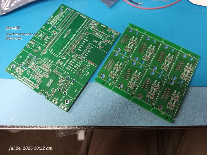
The boards (these big ones are faulty):
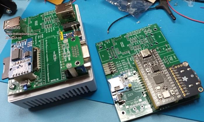
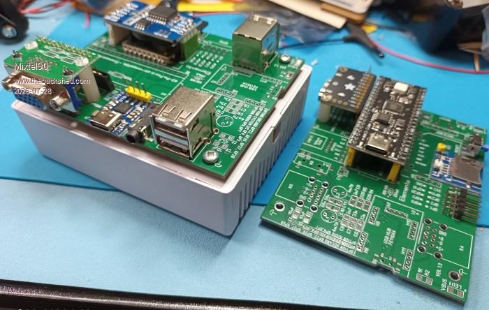
These are "dry run" pics, obviously, to see if bits will fit. They'll give you an idea of the variations that are possible though:
I've not shown the USB hub as I haven't got one to hand.
The RTC module is shown fitted inverted, as originally designed. In theory it just fails to fit inside the case if it plugs in with the battery on top. It could probably be "staked" down solid in some way to make it fit but that would make any access to the SD card socket impossible. Something to consider though, as modifying the RTC module is a bit of a pain.Mick
Mixtel90 Guru Joined: 05/10/2019 Location: United KingdomPosts: 9220
Posted: 11:17am 20 Aug 2026
Copy link to clipboard
Print this post
Having got a bit waylaid by my PC3 adaptations, it's time to get back to Elemento. :)
The first prototype on the new boards is now built and is being tested. So far I'm using a sacrificial YD-RP2040 for the tests and things are going well. I've had SD card, RTC and audio working (that's all I've tested so far). The manual is about ready (but some more pictures might help), as is the circuit diagram. I've not got to the point of cutting out the enclosure yet, although there are templates to mark it out.
GPIO, USB and VGA to test with the YD-RP2040 before I move on to a RP2350 module to test HDMI. Very encouraging so far.
EDIT: USB is working. GPIO pins are correct. Can't find my VGA lead. :( Rookie mistake - reversed the TX and RX connections to the CP2102. :( Edited 2026-08-21 01:01 by Mixtel90Mick
Mixtel90 Guru Joined: 05/10/2019 Location: United KingdomPosts: 9220
Posted: 04:05pm 21 Aug 2026
Copy link to clipboard
Print this post
I reversed the two green signals on the VGA module but it works perfectly if you swap the resistors over, although the silkscreen is incorrect.
HDMI works (although this monitor can be temperamental - that's a known problem that I have to live with until I can justify a replacement). The pins are wrong on the silkscreen though.
I've now tested it with the YD-RP2040 at the cheap end and the Pimoroni Plus 2W at the expensive end. The PSRAM is recognised. I was a little surprised that the Plus 2W doesn't have a Heartbeat LED onboard (or any LEDs for that matter). It makes a change. :)
I've been pleasantly surprised by the audio. Quality isn't great (it is PWM after all - I couldn't spare another pin for I2S) but there is no noise or CPU hiss at all that I can hear, even listening through headphones. It's fine for making noises.
All the problems so far have now, hopefully, been corrected on the design for the 1.3 version. They have also been noted and corrected in the manual.Mick
IanT Senior Member Joined: 29/11/2016 Location: United KingdomPosts: 137
Posted: 12:12pm 22 Aug 2026
Copy link to clipboard
Print this post
I've just purchased a Pimoroni Plus 2 (not the W as it was stock out) Mick and I'm still playing with it. There is an onboard LED connected to GP25 but unfortunately no comforting 'blink' to show MMB is ticking over. It's the same pin as a (vanilla) Pico2 I think, so there must be some other difference that I haven't twigged yet... (not unusual)
However, everything else seems to be working OK with 6.03
Regards,
IanT
matherp Guru Joined: 11/12/2012 Location: United KingdomPosts: 12034
Posted: 12:15pm 22 Aug 2026
Copy link to clipboard
Print this post
MMBasic doesn't automatically configure the heartbeat for boards with the RB2350B. Try OPTION HEARTBEAT ON
Mixtel90 Guru Joined: 05/10/2019 Location: United KingdomPosts: 9220
Posted: 12:27pm 22 Aug 2026
Copy link to clipboard
Print this post
I found the LED, it's very dim and green so I'd missed it. On the W version it's driven from GP0 on the RM2, not GP25. That accounts for me not seeing a heartbeat LED, I suppose. The RM2 isn't configured in any way.
The LED *is* on GP25 on the non-W version.
A bit tight of them not to include some header pins, I thought. It's a pretty expensive board.Mick
IanT Senior Member Joined: 29/11/2016 Location: United KingdomPosts: 137
Posted: 09:24pm 22 Aug 2026
Copy link to clipboard
Print this post
Ahh! (metaphorical light goes on)
Unfortunately, when something doesn't work {quite the way I expect it to} it's very often me that's the "fault". I probably would have figured it out eventually but then maybe not...
Anyway, thank you Peter - I'll turn the Heartbeat on!
IanT
Mixtel90 Guru Joined: 05/10/2019 Location: United KingdomPosts: 9220
Posted: 07:25am 23 Aug 2026
Copy link to clipboard
Print this post
Yesterday saw quite a lot of manual tweaking and a couple of slight PCB changes prior to the gerbers being sorted out. I've proved that the templates for marking out the enclosure can be printed to the correct size, which is something of a relief. :)
Note that this is a cheap build project. There are only three modules: USB hub, RTC and any 40-pin pin-compatible Pico or clone. Only the latter is essential for the first stage. :) It's designed to teach people how to build an electronics project, so you get some through-hole and some SMD soldering (nothing too difficult though). .Mick
At the moment there *may* be limitations, particularly as I need to start some serious cutting of a second enclosure (I made a mess of the first one). However, I'm confident in the PCB now and the manual (a true labour of love!) is probably as complete as it's going to get.
a) It's cheap. You can afford to ruin the first board. b) It will work with *any* 40-pin Pico pin-compatible module. Just plug it in, load a compatible MMBasic and go. c) IMHO it's an ideal little project for someone who would like to test their hardware abilities.
I make no apology for all the Rs and Cs being SMD. That's the way things are going now. At least I've used 1206 size. :)Mick
pwillard Guru Joined: 07/06/2022 Location: United StatesPosts: 347
Posted: 08:57pm 31 Aug 2026
Copy link to clipboard
Print this post
Thanks so much for your effort.
These are also handy cases for other projects. I'll likely be getting more.
Mixtel90 Guru Joined: 05/10/2019 Location: United KingdomPosts: 9220
Posted: 06:38am 02 Sep 2026
Copy link to clipboard
Print this post
I've done a little cutting and drilling on them now and the plastic is pretty good to work. The "click fit" of the base won't tolerate a PCB with inaccurate holes that causes it to warp to any degree, but after quite a lot of fitting and re-fitting it's seems to be pretty resilient.Mick
Volhout Guru Joined: 05/03/2018 Location: NetherlandsPosts: 6184
Posted: 06:51am 02 Sep 2026
Copy link to clipboard
Print this post
Hi Mick,
The manual does not show the USB-C breakout connector, used to connect the HUB, with the green/yellow wires for D+ and D-. It could be in the "modules" section.
Mixtel90 Guru Joined: 05/10/2019 Location: United KingdomPosts: 9220
Posted: 07:13am 02 Sep 2026
Copy link to clipboard
Print this post
Do you mean the little mini plug or the micro-USB to USB-C adapter in the photo? I've suggested using a micro-USB plug with an adapter if needed, that way you can fit any Pico module. Otherwise it's a soldering job to change leads between micro-USB for original Pico and USB-C for the clones.
EDIT:
These are the micro USB plugs that I used: AliExpress
Something like This for the adapter. I think the ones I have came from Amazon or ebay at some time.
You could, of course, use a mini USB-C plug with the opposite adapter, USB-C female to micro USB male, depending on what you can find. Electrically it doesn't matter. :)
Mixtel90 Guru Joined: 05/10/2019 Location: United KingdomPosts: 9220
Posted: 10:21am 14 Oct 2026
Copy link to clipboard
Print this post
Coming up (hopefully) - Elemento 2
Very similar in concept but with some important changes:
No need to unplug the Pico's USB for programming. Just connect the mini USB PROG socket to the computer. A relay changes the USB data connections over and a mosfet disables the supply from the PROG socket if the main USB-C lead is plugged in. The PROG socket only powers the Pico, nothing else is powered up. Disadvantage: this messes up the YD-RP2040 as the diode between 39 and 40 is reversed.
An off-board 3V3 regulator now supplies the 3V3 supply to everything except the Pico, which uses its on-board regulator.
The full size SD card options have gone. You now have a choice of micro SD, as a module or as a push-push socket directly on the board.
The Reset button is always on the front.
Audio is now I2S rather than PWM.
The GPIO port has 4 more pins and is now a polarized 14-pin socket. GP21 has gone (now used for I2S) and has been replaced by additional 3V3 and GND pins, the SQW signal from the RTC (with pullup) and the system I2C pins.
The VBUS light is now PROG (powered from the PROG socket) and the RUN light is now ON (powered from the off-board regulator).
I have the board pretty much laid out now and the schematic is mostly there.
Mini USB rather than micro USB? I have plenty, they are pretty robust, they are smaller than a micro USB on a breakout board and it's possible to solder them reasonably easily. Leads are still easy to get. Soldering micro USB by hand is virtually impossible.
------------------------------
I've also been doing a lot of work designing a 3D printed case for this board. Although it will still fit the original AliExpress one, some people may prefer something a bit nicer. It's not ready yet though.Mick

 Notice. New forum software under development. It's going to miss a few functions and look a bit ugly for a while, but I'm working on it full time now as the old forum was too unstable. Couple days, all good. If you notice any issues, please contact me.


 Print this post