
|
|
Forum Index : Microcontroller and PC projects : picomite mmbasic howto
| Author | Message | ||||
| Volhout Guru Joined: 05/03/2018 Location: NetherlandsPosts: 3552 |
Picomite MMBasic has a wealth of features that most of us don't even know. Some can be very handy, if you know how to use them. This thread is intended for everyone to contribute and show in small educational programs how things can be done in picomite MMbasic. I will kick off this thread by showing a very elementary VU meter. It shows the principles of: - measuring multiple ADC samples automatically ADC OPEN freq,1,INT_RDY ADC START a() You can open a ADC channel (in this case ADC 1 at GPIO pin 26) to perform a range of automated measurements at repetition rate "freq", and when done jump to interrupt routine INT_RDY. This command replaces the SETPIN gp26,AIN command. The ADC start a() tells the ADC to start capturing te size of array a() (that has been DIM'ed before) and when ready filling the array, it will jump to the interrupt routine. In the interrupt routine, you can process the array. - calculating the RMS value of these samples Once you have an array of samples, you can calculate the RMS value of the signal at the samples (i.e. the audio level) by using MATH functions. rms = MATH(SD a()) It happens that the standard deviation (statistical function) uses the exact same formulas as the calculation of the AC RMS value. So that is very fast and simple. - showing the spectrum (part of it) of the signal at the ADC input When you have an array of measurement samples from the ADC it is simple to calculate the spectrum from it using another MATH function: MATH FFT MAGNITUDE a(),b() Will convert the sample data in the a() array to spectral data in the b() array. The fft spectrum data is "mirrored", so you only have to analyze half of the b() array to find the magnitude of the spectrum bins. In below program we only analyze 100 bins of the (512 / 2 =) 256 bins, because I was not interested in the rest. Note that a() and b() must be 2^n size (i.e. 32,64,128,256,512 etc..) Below program uses 1 more trick: in the ADC interrupt routine the ADC is re-started with another array (ping-pong), so you can process the RMS and FFT while the ADC continues sampling and stores data in a different array. You never miss a sample..... 'ping-pong ADC and calculate RMS value and fft 'runs on picomite VGA in mode 1 (640x480 monochrome) 'system parameters Option base 1 n=512 'samples Dim a(n),b(n) 'ping pong buffers Dim c(n),d(n) 'processing buffer 'hardware parameters offset = -1.66 'hardware default freq = 2000 'ADC sampling frequency 'test signal generated from PWM SetPin gp0,pwm PWM 0,50,50 '50Hz, 50% d.c. 'open the ADC and start first conversion 'SetPin gp26,ain ADC OPEN freq,1,INT_RDY ready=0:pingpong=1 ADC START a() 'main routine Do 'every n/freq a new buffer is filled with samples and ready flag raised 'we have time to process the data. Using math commands we gain time 'rms is 4ms/512 samples, fft = 44ms/512 samples, plotting the graph consumes most time If ready Then If pingpong Then MATH ADD b(),offset,c() Else MATH ADD a(),offset,c() EndIf rms = Math(SD c()) 'math(sd a()) does all the math to 'calculate rms from an array CLS Print @(480,0)"RMS = ";rms*scale ready=0 'fft calculate magnitude MATH FFT MAGNITUDE c(),d() scale=(MM.VRES-10)/n MATH SCALE d(),scale,d() 'scale to match samples on 470 vertical 'resolution 'fft spectrum show bars=100:wdth=Int(MM.HRES/bars) For i=2 To bars'n/2 - 1 BOX i*wdth,470-d(i),wdth,d(i) Next i EndIf Loop While Inkey$="" Save compressed image "fft_bars.bmp" End 'interrupt routine Sub INT_RDY If pingpong Then ADC START b() Else ADC START a() EndIf pingpong=1-pingpong ready=1 End Sub Below is a picture of the captured spectrum from a PWM running on GP0, that is going through a 10k/100nF low pass filter (to change it into a triange-like waveform). The spectrum clearly shows the 50Hz base frequency, and 150Hz, 250Hz and 350Hz harmonics. Totals spectrum is 0-400Hz. 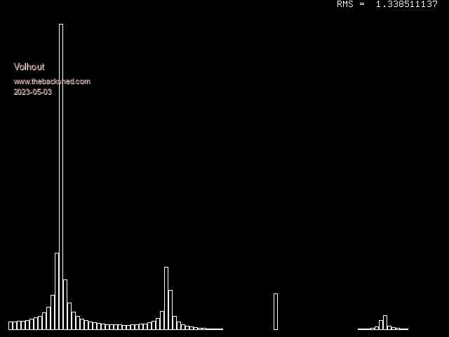 The program uses 2 more functions that might come in handy: MATH ADD a(),x,c() where a fixed value x is added to each of the samples in the a() array, and the result copied to the c() array. In my case the ADC input is around half Vdd (1/2 * 3.3V = 1.65V), so adding -1.65V changes all values around zero. MATH SCALE a(),s,b() scales the FFT results in the a() array to the vertical resolution of the screen. Each value in the a() array is multiplied by value s and put into array b(). Happy programming Volhout Edited 2023-05-03 06:04 by Volhout PicomiteVGA PETSCII ROBOTS |
||||
| homa Senior Member Joined: 05/11/2021 Location: GermanyPosts: 242 |
 Thank you for describing that so good! Thank you for describing that so good!Matthias |
||||
| Amnesie Guru Joined: 30/06/2020 Location: GermanyPosts: 382 |
Running into some problems, since GP0 is already in use on my PCB I changed it from: 'test signal generated from PWM SetPin gp0,pwm PWM 0,50,50 '50Hz, 50% d.c. To: 'test signal generated from PWM SetPin gp1,pwm PWM 0,50,50 '50Hz, 50% d.c. And get: [16] PWM 0,50,50 '50Hz, 50% d.c. Error : Pin not set for PWM But why? I am setting GP1 as PWM output, it is using channel 0B so this should work: PWM 0,50,50 > option list PicoMiteVGA MMBasic Version 5.07.08b15 OPTION SYSTEM I2C GP14,GP15 OPTION COLOURCODE ON OPTION KEYBOARD GR OPTION CPUSPEED (KHz) 252000 OPTION SDCARD GP13, GP10, GP11, GP12 OPTION AUDIO GP6,GP7, ON PWM CHANNEL 3 > Greetings Daniel |
||||
| phil99 Guru Joined: 11/02/2018 Location: AustraliaPosts: 1790 |
change PWM 0,50,50 toPWM 0,50,,50 to skip over Ch 0A and use Ch 0B. |
||||
| Amnesie Guru Joined: 30/06/2020 Location: GermanyPosts: 382 |
Thank you, this solved the problem, I wished It would be more examples in the manual, I already looked at Page 87 and tried to understand it, but "PWM channel, frequency,[dutyA] [,dutyB][,phase][,defer]" even in the text it is not really clear for me: it states: "You can output on either PWMnA or PWMnB or both for each channel - no restriction. " okay, but this does not tell me how to use it! I wished there would be more basic examples... Even in the manual there is nothing for this specific case, just a PIO example with PWM. A lot to learn, thank you all! -Daniel |
||||
| matherp Guru Joined: 11/12/2012 Location: United KingdomPosts: 8592 |
PWM channel, frequency,[dutyA] [,dutyB][,phase][,defer] If you look at the diagram of pin usage you will see that pin 2 (gp1) is PWM0B In the command syntax above there is a comma after the frequency that is not in square brackets - i.e. it is mandatory. So if using a "B" channel you can omit the "A" frequency but the comma must be there. There is then a comma in the optional "B" frequency field. Therefore to use just the "B" channel the command must be as phil99 has indicated The request for more examples is common AND totally impracticable as there are so many variants and the manual is already huge Edited 2023-09-04 23:52 by matherp |
||||
| RonnS Senior Member Joined: 16/07/2015 Location: GermanyPosts: 120 |
thank you Volhout for this extensive and instructive explanation Ron |
||||
| Mixtel90 Guru Joined: 05/10/2019 Location: United KingdomPosts: 5735 |
Knowing where to stop with a manual is *very* difficult. If you try to explain everything in fine detail then 95% of readers will be bored to tears - most of that content will only be of interest to beginners. Geoff wrote "Getting Started With the Micromite" to help beginners. It's not really aimed at the PicoMite but it's a good general purpose guide to MMBasic anyway. Perhaps that is what needs expanding to take in at least some of the more recent aspects of MMBasic? Perhaps make it more of a "Getting Started with MMBasic"? In this particular case the information, or how to obtain it, is there at the top of the Commands section: "Square brackets indicate that the parameter or characters are optional". Realizing that commas between optional data are still mandatory isn't actually stated as such. Mick Zilog Inside! nascom.info for Nascom & Gemini Preliminary MMBasic docs & my PCB designs |
||||
| stanleyella Guru Joined: 25/06/2022 Location: United KingdomPosts: 1647 |
Hi Daniel. I'd like more examples in the manual but if after an hour I can't understand something then I ask on this forum and someone more knowledgeable will kindly offer help including examples. The manual is 150+ pages cos mmbasic has so many things to explain! If you only use mmedit as I do, the pages for the inbuilt editor are irrelevant. I don't know if you can edit the manual for one's own use. |
||||
| Amnesie Guru Joined: 30/06/2020 Location: GermanyPosts: 382 |
You guys are right! Of course the manual is one of the best I've ever seen. What I mean was a totally different thing. Let me correct myself: I'd wish there would be a "how to" tutorial-like book from "noob to pro". Of course this is a huuuge amount of work. This always will be a dream - I know. This is why this forum here is so important and everyone is being so kind and helpful! So thank you all. See you - with my next dumb question -   Greetings Daniel |
||||
| Mixtel90 Guru Joined: 05/10/2019 Location: United KingdomPosts: 5735 |
What would you say was "noob" level? Never used any BASIC before, only used BASIC on ANOther (totally incompatible) computer, used MMBasic but only on a Micromite? They are rather different starting points - and that's only the beginning. :) Seriously, a book like that can only exist in your imagination, I'm afraid. If you are a noob at MMBasic then I suggest reading the PicoMite manual Appendix F or PicoMite VGA manual Appendix H before you do anything else. Work through the examples (where possible). Mick Zilog Inside! nascom.info for Nascom & Gemini Preliminary MMBasic docs & my PCB designs |
||||
| stanleyella Guru Joined: 25/06/2022 Location: United KingdomPosts: 1647 |
noob to pro is maybe learn what you want as you need it, not learn the whole manual. I found transferring working code from another basic to mmbasic unable to do until forum help. I think noob to pro would be a lot more effort than you imagine. Where would you change from noob code to pro. Noob code is actually getting a glcd to draw something, not flash a led. flashing led... far out.. not. Glcd and trig? make it look interesting and a display working would be a thrill to not lead to boredom, imho. Try writing one if you are a noob and write your experiences so others can share what you've learnt. I think that's what we do on the forum, share working'ish code:) |
||||
| lizby Guru Joined: 17/05/2016 Location: United StatesPosts: 3016 |
It's not a manual, but there are a lot of code examples on fruitoftheshed.com, mostly by CaptainBoing. Much of it is generic, and where not, focused on the Micromite (and mostly not including MMBasic developments of the past several years). A limited selection regarding F4 and Picomite here Maxi/MicroMite variations: MaxiMite, Colour MaxiMite (CMM/CMM1), MX150 MicroMite (MM1), MX170 MicroMite (MM2), MX470 MicroMite Plus (MM+), PIC32MZ MicroMite eXtreme (MMX), MMBasic for DOS, Pi-cromite (pi-based, no longer supported, may work for non-gpio uses), Armmite H7, Armmite L4, Armmite F4, Colour Maximite 2 (CMM2), Picomite, MMB4L (Linux--currently in Alpha), PicoMiteVGA, MMBasic for Windows (MMB4W)--currently in Beta, WebMite (Pico-based). PicoMite, Armmite F4, SensorKits, MMBasic Hardware, Games, etc. on fruitoftheshed |
||||
| Turbo46 Guru Joined: 24/12/2017 Location: AustraliaPosts: 1593 |
There is Geoff's Getting Started with the Micromite. You can download it from here. It is for the Micromite but would still be a very useful introduction. Bill Keep safe. Live long and prosper. |
||||
| matherp Guru Joined: 11/12/2012 Location: United KingdomPosts: 8592 |
Spent a fun few minutes playing with ideas for volhout's PETSCII program and thought this might be more generally useful PROBLEM Store sprites efficiently and plot them on the screen (works with PicoMiteVGA or F or L framebuffer on any PicoMite) Solution: Store the sprites as CSubs (1 nibble per pixel) Use memory copy to move the required sprite to the screen Hopefully the attached is obvious from the comments MODE 2 Do plot Rnd*3,Rnd*14,Rnd*10 'demo Loop ' ' routine to display sprites, currently optimised for 24x24 pixels but easy to change ' Sub plot(s%, xin%, yin%) 'sprite number, x_tile position, y_tile position Static w%=MM.HRes\2 Static c%=Peek(cfunaddr test) Local yy%, y% = yin% * 24 * w% Local x% = xin% * 12 Local b% = MM.Info(writebuff) +x% + y% Local a% = c% + s% * 288 For yy% = 0 To 23 Memory copy a%, b%,12 Inc b%,w% Inc a%,12 Next End Sub ' CSub test '24x24 sprites (should be saved in the library) 00000000 'sprite 0 FFFFFFFF 88888888 44444444 22222222 66666666 88888888 CCCCCCCC FFFFFFFF 55555555 FFFFFFFF 88888888 44444444 22222222 66666666 88888888 CCCCCCCC FFFFFFFF 55555555 FFFFFFFF 88888888 44444444 22222222 66666666 88888888 CCCCCCCC FFFFFFFF 55555555 FFFFFFFF 88888888 44444444 22222222 66666666 88888888 CCCCCCCC FFFFFFFF 55555555 FFFFFFFF 88888888 44444444 22222222 66666666 88888888 CCCCCCCC FFFFFFFF 55555555 FFFFFFFF 88888888 44444444 22222222 66666666 88888888 CCCCCCCC FFFFFFFF 55555555 FFFFFFFF 88888888 44444444 22222222 66666666 88888888 CCCCCCCC FFFFFFFF 55555555 FFFFFFFF 88888888 44444444 22222222 66666666 88888888 CCCCCCCC FFFFFFFF 55555555 'sprite 1 FFFFFFFF 88888888 44444444 FFFFFFFF 88888888 44444444 FFFFFFFF 88888888 44444444 FFFFFFFF 88888888 44444444 FFFFFFFF 88888888 44444444 FFFFFFFF 88888888 44444444 FFFFFFFF 88888888 44444444 FFFFFFFF 88888888 44444444 FFFFFFFF 88888888 44444444 FFFFFFFF 88888888 44444444 FFFFFFFF 88888888 44444444 FFFFFFFF 88888888 44444444 FFFFFFFF 88888888 44444444 FFFFFFFF 88888888 44444444 FFFFFFFF 88888888 44444444 FFFFFFFF 88888888 44444444 FFFFFFFF 88888888 44444444 FFFFFFFF 88888888 44444444 FFFFFFFF 88888888 44444444 FFFFFFFF 88888888 44444444 FFFFFFFF 88888888 44444444 FFFFFFFF 88888888 44444444 FFFFFFFF 88888888 44444444 FFFFFFFF 88888888 44444444 'sprite 2 CCCCCCCC FFFFFFFF 55555555 CCCCCCCC FFFFFFFF 55555555 CCCCCCCC FFFFFFFF 55555555 CCCCCCCC FFFFFFFF 55555555 CCCCCCCC FFFFFFFF 55555555 CCCCCCCC FFFFFFFF 55555555 CCCCCCCC FFFFFFFF 55555555 CCCCCCCC FFFFFFFF 55555555 CCCCCCCC FFFFFFFF 55555555 CCCCCCCC FFFFFFFF 55555555 CCCCCCCC FFFFFFFF 55555555 CCCCCCCC FFFFFFFF 55555555 CCCCCCCC FFFFFFFF 55555555 CCCCCCCC FFFFFFFF 55555555 CCCCCCCC FFFFFFFF 55555555 CCCCCCCC FFFFFFFF 55555555 CCCCCCCC FFFFFFFF 55555555 CCCCCCCC FFFFFFFF 55555555 CCCCCCCC FFFFFFFF 55555555 CCCCCCCC FFFFFFFF 55555555 CCCCCCCC FFFFFFFF 55555555 CCCCCCCC FFFFFFFF 55555555 CCCCCCCC FFFFFFFF 55555555 CCCCCCCC FFFFFFFF 55555555 End CSub |
||||
| lizby Guru Joined: 17/05/2016 Location: United StatesPosts: 3016 |
I don't have much of a handle on this--is an updated version of the firmware needed, or a change in code for a picomite? > load "spritetest.bas" > run Error: Invalid address - resetting PicoMite MMBasic Version 5.07.08b15 Copyright 2011-2023 Geoff Graham Copyright 2016-2023 Peter Mather > PicoMite, Armmite F4, SensorKits, MMBasic Hardware, Games, etc. on fruitoftheshed |
||||
| matherp Guru Joined: 11/12/2012 Location: United KingdomPosts: 8592 |
No, but as per my post So to use it on a Picomite it must operate on a framebuffer FRAMEBUFFER create FRAMEBUFFER write F i%=0 Do plot Rnd*3,Rnd*12,Rnd*9 'demo If i% Mod 50 = 0 Then FRAMEBUFFER copy f,n 'update the screen every logical ope ration Inc i% Loop |
||||
| lizby Guru Joined: 17/05/2016 Location: United StatesPosts: 3016 |
Ok, looks good. Thanks. On ILI9488:  PicoMite, Armmite F4, SensorKits, MMBasic Hardware, Games, etc. on fruitoftheshed |
||||
| Volhout Guru Joined: 05/03/2018 Location: NetherlandsPosts: 3552 |
MCP4161 The ---- Digital non-volatile potmeter ---- I think most of you know these parts: 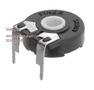 They where used abundantly in analog electronics in the 80's. Technical blabla: For a project that requires a very low noise instrumentation amplifier, we needed to divert from the integrated instrumentation amplifiers, like TI INA111, and use lower (input current noise) separate amplifiers like TI OPA2188, or even better AD8572. But that requires very accurate resitors. The commercially available (and economically viable) parts are 0.1% tolerance, and have below 15ppm temperature drift. But 0.1% resistors give you only 60dB common mode rejection in the instrumentation amplifier. So additional tuning (to 0.01%) was needed. The idea was to use a potmeter. The manufacturing site did not like that (mechanical adjustment), so we opted for a digital potmeter. 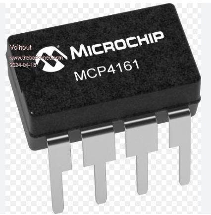 The MCP4161 is a digital potmeter, that is NON-VOLATILE. You can adjust it in circuit, then disconnect the SPI bus from it, and it will keep the last settingprogrammed in EEPROM at each successive power up. I worked out a circuit for a programmer (you need +10V to program the parts EEPROM) based on a picomite. 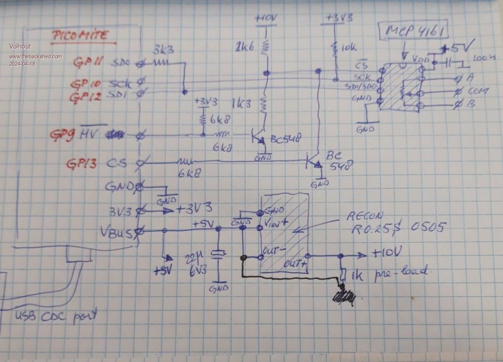 The ciruit was build on veroboard, and below photo shows the circuit before the shrink sleeve was put on it. 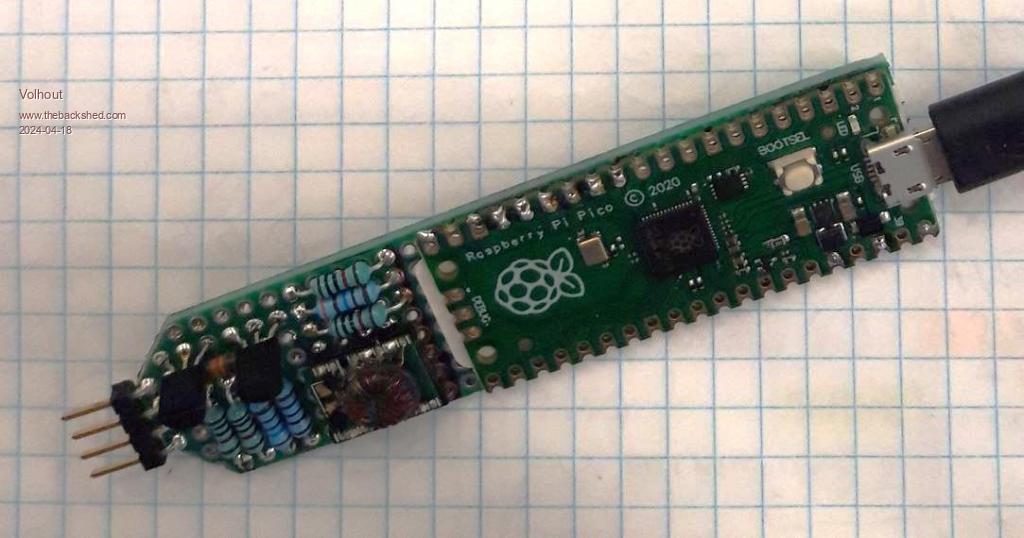 The picomite when attached to the PC will allow you to tune the potmeter with + and - buttons on the keyboard. Then write the current value into EEPROM with "w". The code: 'control of MCP4161 non-volatile potmeter 'Versions ' 0.1 Control of volatile potmeter up and down, read status ' 0.2 CSn inverted prepare for EEPROM prog ' 0.3 Write potmeter wiper value permanent after tuning in RAM ' 0.4 Help added, cleanup 'open SPI channel SetPin gp12, gp11, gp10, SPI2 'RX,TX,CLK 'hardware pullup 10k on SCK forces chip in mode=11. 'This is mode 3 on picomite,use 8 bit SPI transfers SPI2 open 100000,3,8 '16 bit: 2x8bit = data transfer 'bit 15..12 = register address send to device 'bit 11,10 = cmd C1/C0 (00=write, 01=incr, 10=decr, 11=read) 'bit 9 = CMD_ERR ? or data 'bit 8..0 = data '8 bit transfer = commands (up/down/write protect, wiper lock) 'bit 7..4 = register address send to device 'bit 3,2 = cmd C1/C0 (00=write, 01=incr, 10=decr, 11=read) 'bit 1 = CMD_ERR ? or data 'bit 0 = data 'note: 8 bit transfer is identical to 15...8 of 16 bit transfer 'CSn signal (active L, program when CSn=+12V through external HW) SetPin gp13,dout:Pin(gp13)=0 'CSn inverted setpin gp9,dout:pin(gp9)=1 'CSn_Vihh inverted ' some defines up8=&b00000100 'wiper 0 incr dn8=&b00001000 'wiper 0 decr st16=&b01011111 'read status register (data bits high, open drain status read) nww0=&b00100000 'write NV wiper 0 register nrw0=&b00101100 'read NV wiper 0 register ww0=&b00000000 'write wiper 0 register rw0=&b00001100 'read wiper 0 register 'user manual print "Interface to program MCP4161 non volatile potmeter" print "Use + and - keys to adjust potmeter wiper position" print "Use w key to write wiper position in non-volatile memory" print "Use r key to verify written value, s for status register" 'check if MCP4161 device attached do rd1=0:rd2=0 stat if rd2=255 then print "-------- no device found --------------" pause 1000 loop while rd2=255 print "SPI device found, start potmeter control" Do a$=Inkey$ Select Case a$ Case "+" 'potmeter up up read_w0 'stat Case "-" 'potmeter down dwn read_w0 'stat Case "s" 'read status register stat case "w" write_nv case "r" read_nv Case Chr$(27) '<esc> Exit End Select Loop End 'this sub prints the status register content Sub stat Pin(gp13)=1 'CSn low rd1=SPI2(st16) 'SPI command rd2=SPI2(255) 'SPI data Pin(gp13)=0 'CSn high Print "status = "+Right$("000"+Bin$(rd1*256+rd2),16) End Sub 'this sub increments the wiper position and reads back value Sub up 'perform UP command Pin(gp13)=1 'CSn low rd=SPI2(up8) 'send UP command for wiper 0 'Print "cmd="+Right$("0000000"+Bin$(rd),8) Pin(gp13)=0 'CSn high End Sub 'this sub increments the wiper position and reads back value Sub dwn 'perform UP command Pin(gp13)=1 'CSn low rd=SPI2(dn8) 'send DOWN command for wiper 0 'Print "cmd="+Right$("0000000"+Bin$(rd),8) Pin(gp13)=0 'CSn high End Sub 'read volatile wiper register and display sub read_w0 Pin(gp13)=1 'CSn low rd1=SPI2(rw0) 'SPI command to read wiper 0 rd2=SPI2(255) 'SPI data Pin(gp13)=0 'CSn high 'Print "SPI="+Right$("000"+Bin$(rd1*256+rd2),16) print "wiper = "+str$(rd2) end sub 'this sub writes value v non voltile wiper 0 register 'value v is read from volatile wiper 0 register sub write_nv 'read wiper 0 register Pin(gp13)=1 'CSn low rd1=SPI2(rw0) 'SPI command rd2=SPI2(255) 'SPI data Pin(gp13)=0 'CSn high 'process data rd=rd1*256+rd2 'Print "SPI="+Right$("000"+bin$(rd),16) 'print "wiper="+str$(rd2) v=rd2 'v=wiper value 'write data to NV wiper register pin(gp9)=0 'CSn = Vihh rd1=SPI2(nww0) rd2=SPI2(v) pin(gp9)=1 'CSn = Vdd 'Print "SPI="+Right$("000"+Bin$(rd1*256+rd2),16) print "wiper = "+str$(rd2)+" written to NV memory" end sub 'this sub reads from eNV wiper 0 register sub read_nv Pin(gp13)=1 'CSn low rd1=SPI2(nrw0) 'SPI command rd2=SPI2(255) 'SPI data Pin(gp13)=0 'CSn high rd=rd1*256+rd2 'Print "SPI="+Right$("000"+bin$(rd),16) print "NV_wiper = "+str$(rd2) end sub PicomiteVGA PETSCII ROBOTS |
||||
| Volhout Guru Joined: 05/03/2018 Location: NetherlandsPosts: 3552 |
Thermal Camera's This post contains 2 programs that can be used to read temperatures from Melexis thermal camera modules. The modules are from SEED STUDIO Grove series. The camera's where selected to evaluate if small SMT resistors heating up can be detected in series production. For this to be successfull you either need a thermal camera the good resulution (such as a Fluke TIS-45, which cost a fortune), of a camera which is small, and can be mounted close to the object under test. That camera should have a small opening ange to distinguish between one component and another. MLX90614-DCI A single pixel camera, with 5 degrees opening angele. 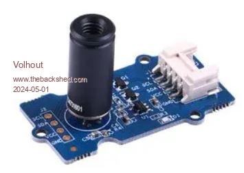 This camera outputs degrees K(Kelvin) on it's I2C bus. Attached program can be used to log 60 readings (1 second each) to a log file. Running on PicoMiteVGA. A photo of the setup (measuring the component edge of a larger component). 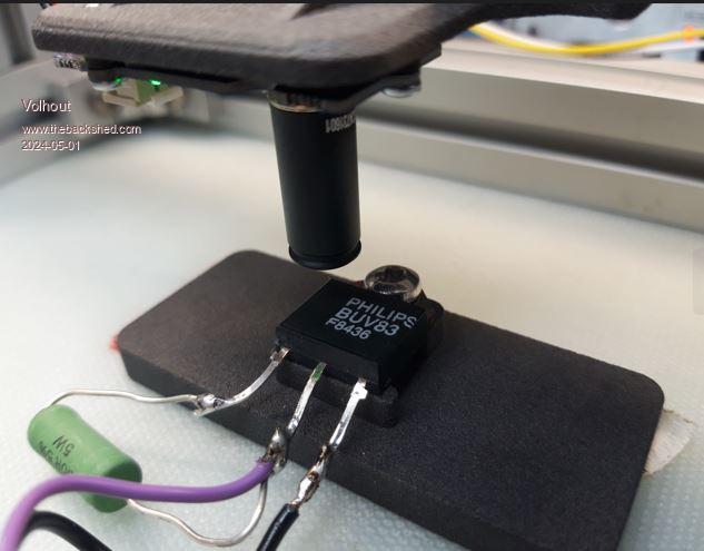 The MMbasic program MLX90614-DCI_V02.zip MLX90621-BAB 16x4 pixel camera with 60 degrees opening angel (around 4 degrees per pixel). This camera outputs raw voltage per pixel, and you need to read calibration constatnts from it's EEPROM, do a lot of math, to convert to degrees C. This math is included in the below MMBasic program. 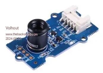 The module I received from Farnell has a flaw. It powers the MLX90621 chip with 3.3V where the calibration data in EEPROM is for 2.6V operation (says datasheet). And indeed, reading where wrong. After modifying the module to 2.6V reading where far more accurate. 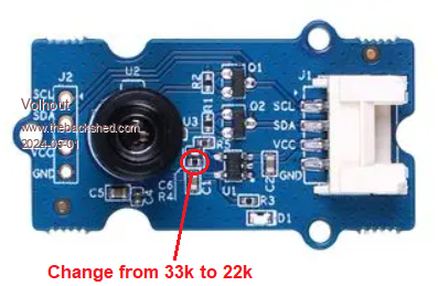 The MMBasic program does the same logging, and also shows the pixel temperatures on the VGA screen. 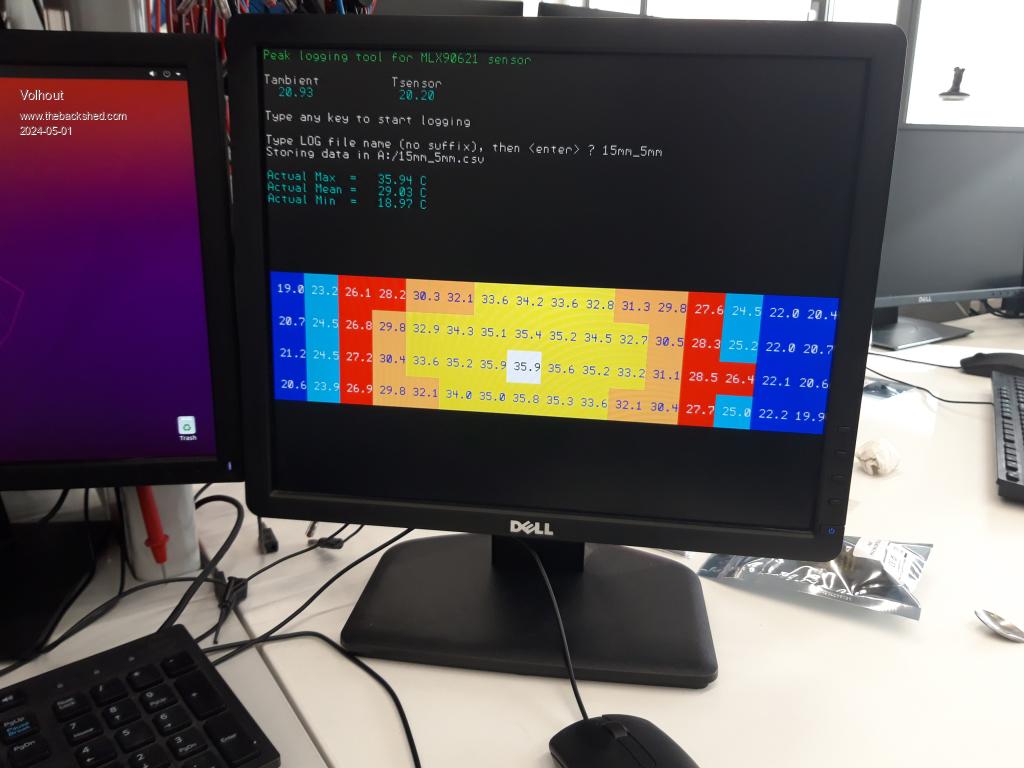 The MMBasic program MLX90621_V03.zip This code is made to "do the job". It is not perfect or formatted perfect. But can be used as an example of how to interface with these modules. Volhout PicomiteVGA PETSCII ROBOTS |
||||
