
|
|
Forum Index : Microcontroller and PC projects : Aquarium (or general purpose) controller
| Page 1 of 3 |
|||||
| Author | Message | ||||
| Mixtel90 Guru Joined: 05/10/2019 Location: United KingdomPosts: 8976 |
This is my current project between other things. :) It's a board (designed to fit a CMM2 case) that can be used for general purpose control. 2 DC outputs with ON-OFF-AUTO switches (selectable for 5V or 12V) -- (intended for white lighting and CO2 dosing solenoid 3 DC outputs -- (intended for PWM LED lighting) 1 AC mains relay output with ON-OFF-AUTO switching -- (intended for airstone pump) 2 AC mains relay outputs with OFF-ON switches and a crude form of relay coil monitoring -- (intended for filter pump and heater) 1 input for DS18B20 temperature sensor Socket for RTC Socket for SDcard reader Audio buzzer RGB indicator LED on front panel 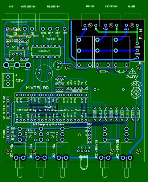 The idea is that it gets rid of a lot of 13A plugs & sockets, giving easy control of things (like shutting off the filter pump for cleaning) without bothering about wet hands. All switching is at 3.3V or 12V and all the toggles are connected to mains earth. I couldn't find small mains outlet connectors so I settled for 3.81 pitch pluggable terminals as these are not easy to touch. With hindsight I should have put links on the PCB to disable the relay for any unused mains output, but never mind. The plugs for the mains sockets are screwless types as the wire exits from the back. A bit of heatshrink sleeve should make them completely touch-proof, if a bit lacking in cable retention! As you can see, this could be used for all sorts of things where you just want a bit of a control system. It wouldn't take much to modify the design if you needed auto control of the two switched mains relays, but I deliberately wanted them safe. The tank can be run even without the Pico if necessary. Using a Pico W in this would allow me to update the program over Telnet, so no access is needed to the USB connector once up and running. That's one less hole in the box. The mains connections are reduced from: modified 6-way extension block hard-wired 2-pole timer two 2-way mains adapters plugs for: heater, filter pump, airstone pump, CO2 solenoid, RGB light, white light, work light, standby water heater to standard 4-way extension block plugs for: 12V PSU, mains supply, work light, standby water heater Mick Zilog Inside! nascom.info for Nascom & Gemini Preliminary MMBasic docs & my PCB designs |
||||
| CaptainBoing Guru Joined: 07/09/2016 Location: United KingdomPosts: 2171 |
I did an aquarium controller years ago with a PIC16F877. It was very good, but programming in assembler was quite awkward at times, especially as I got rusty between sessions. It was a few years before I would discover MicroMites or a decent compiled basic - like GCB. how easy that would have made things! I have a circuit diagram somewhere and some pics of the tank if anyone is interested. The tank was a 550ltr sea tank with a 60ltr sump in the bottom of the cabinet fed with two large Eheim cannister pumps (water in, water out). The level of the sump was balanced by sensing the water level in the sump. Because the tubes tended to siphon when the pumps were off, there was also a "siphon blow" air-line to each of the "walking sticks" so the thing didn't empty the tank into your house in the even of some failure - it had a NiMh rechargeable battery to allow the electronics to do this in event of power failure. I monitored temperature directly in the tank and two heaters set on maximum. You'll never get them balanced, always one will be permanently on and the other off - also, if a heater fails the other stands a good chance at mitigating the water temperature. These were operated via an opto-relay for quietness. The water level in the sump was measured by a float with a magnet in it which operated three hall effect sensors, one at the bottom which was "sump empty", the the one at the top which was "sump full" and then the one at the very top which was "overflow imminent". I had two modes of operation; the first measured the time between full-empty-full and attempted (with some success) to keep the sump just under full by balancing the input and output pumps, and another which drained then filled the sump; which allowed all the rocks and their resident beasties in the sump to get air-time and so simulating tides at a substantially accelerated rate - some bugs on the filter rocks benefit from it. The float was made by melting two wax "tea light" candles (they are made from powdered wax and so porous), inverted and melted together to give a solid "puck". I drilled two 8mm holes through at 0° & 180° and then a blind hole on the side at 90° that would take a neodymium magnet. Dropped it in then sealed it in with more wax so it couldn't react with the salt water. The puck was then slotted onto two plastic rods fixed to the sump at the top so the wax float could slide up and down with the water level. The Hall effect sensors were then mounted on the outside of the glass with silicon. When the float got to a level, the magnet activated the hall switch and that was picked up by the controller. In the event the sump continued to fill, the float got up to the overflow sensor and (after some s/w attempts to recover the situation) the solenoid valves operated allowing water into the piping and breaking the siphon. The two siphon blow solenoid valves were controlled via power transistors. It all worked quite well for a number of years. I tweaked the software over time but I only automated the things that needed it. Stuff like power heads/air stones were left to do their thing. I never did anything about the lights, they just came on and off with a timer - it was only years later (after I had got out of the hobby) that I made a nice light controller for a friend which simulated a full day cycle from ghostly blue overnight to dawn, full sun, dusk and night again. I have some bits and bobs on TBS that cover that. |
||||
| Mixtel90 Guru Joined: 05/10/2019 Location: United KingdomPosts: 8976 |
This tank is tiny (only 20l / 5 gal US) and doesn't really warrant complexity. What's more, it's an ordinary tropical (but will be planted) tank. However, it's all I have space for. :) It doesn't stop the electrics being a pain though, hence this project. The 6-way extension block is mounted on a board with the timeswitch. It's been modified to give two sockets on each timeswitch channel and two always on. It works well enough but there's a lot of wiring that I really want to reduce. I can't hide it anywhere apart from behind the tank itself. I used to have a 3ft tropical tank and a 4ft cold water (with a serious external power filter) for my goldfish. :) One of them turned out to be a Koi and it would take pond pellets out of my fingers. :) I don't have the space for such things now. The PCB has a fancy trick up its sleeve. If you fix it into a CMM2 case using just the fixing holes underneath the switches you can then mark/drill all the other fixing points and access holes for the buttons. All the mounting spacers will line up automatically then. :) It was cheaper to do this than make a proper size PCB. Mick Zilog Inside! nascom.info for Nascom & Gemini Preliminary MMBasic docs & my PCB designs |
||||
| Volhout Guru Joined: 05/03/2018 Location: NetherlandsPosts: 5998 |
Hi Mick, After a power dip, the cpntroller should pick up correctly. Either use a webmite with NTP, or add a socket dor a RTC. Just a tip... Volhout. PicomiteVGA PETSCII ROBOTS |
||||
| Mixtel90 Guru Joined: 05/10/2019 Location: United KingdomPosts: 8976 |
Yep. There's a RTC socket (just behind the LED) and a Pico W. I might set it up to look for NTP at boot, try a second time and if that fails get the time from the RTC and indicate a fault. It's about the best I can do, I think. I've not tried this before. It means only grabbing the RTC time on demand, not automatically. Power fail on a small tank is never good. There isn't as much thermal capacity in the volume of water as there is in a larger one. Luckily we very rarely get power cuts that last more than a few mins. I was surprised to see that you can now get low power 5V aquarium heaters that would run from a power bank for a short while. I suppose a ceramic resistor with leads covered in silicon gunk would do just as well. :) Mick Zilog Inside! nascom.info for Nascom & Gemini Preliminary MMBasic docs & my PCB designs |
||||
| Volhout Guru Joined: 05/03/2018 Location: NetherlandsPosts: 5998 |
Hi Mick, Why are there diodes at the coils of the 2 rightmost relays ? You connected pin 9 of the ULN2003 to +12V, so the diodes would not be needed. EDIT: Oops... these relays are controlled by switches. Sorry... Volhout Edited 2024-03-04 20:12 by Volhout PicomiteVGA PETSCII ROBOTS |
||||
| Mixtel90 Guru Joined: 05/10/2019 Location: United KingdomPosts: 8976 |
Those two are directly switched by the RH OFF-ON toggle switches, not via the ULN2003. I only used relays to give isolation from the toggles, which are going to be operated by wet fingers! Mick Zilog Inside! nascom.info for Nascom & Gemini Preliminary MMBasic docs & my PCB designs |
||||
| Volhout Guru Joined: 05/03/2018 Location: NetherlandsPosts: 5998 |
Hi Mick, Power bank heating may not bring you much.  Minimum for a small fish tank is 25 watt. Appart from capacity (VA) it will be hard to find a power bank that can deliver 5A (5V). Typical power bank will be (internal) 3.7V at 3-5A (12-18VA) and may deliver 2A... Volhout PicomiteVGA PETSCII ROBOTS |
||||
| Mixtel90 Guru Joined: 05/10/2019 Location: United KingdomPosts: 8976 |
Oh, I agree. I use a 25W in this. The idea is to use a low power heater, possibly even less than 5W, just to slow down the tank cooling to gain some extra time. Even if it only gave 30mins longer it would be worthwhile. Even this small tank is probably ok for an hour anyway. I tried a 15W heater in this and it did manage to heat the tank, but it was slow. A little standby heater would never have to cope with that. Mick Zilog Inside! nascom.info for Nascom & Gemini Preliminary MMBasic docs & my PCB designs |
||||
| Mixtel90 Guru Joined: 05/10/2019 Location: United KingdomPosts: 8976 |
Finally, some more info. :) Here's the circuit diagram: circuit.pdf And here's the Gerbers: aq-ctrl.zip If anyone wants to modify it for their own purposes, Here's the SL6 file so you can edit the layout yourself: aquarium control SL6.zip This needs Sprint Layout 6.0. The PCB is 100mm square so that it is in "the cheap zone" for JLCPCB. There is no manual or BOM as such. There are a few details on the circuit. Mick Zilog Inside! nascom.info for Nascom & Gemini Preliminary MMBasic docs & my PCB designs |
||||
| Volhout Guru Joined: 05/03/2018 Location: NetherlandsPosts: 5998 |
Hi Mick, For us, mainland Europeans, it looks very strange to see a design that does not have a mains fuse. I know in UK you have mains fuses in the power plug, but these may be rated higher that the PCB traces can handle (or the relay contacts for that matter), so you would need to have a fuse rated for the product...right ? Like a 2A/3.15A/4A fuse. Volhout PicomiteVGA PETSCII ROBOTS |
||||
palcal Guru Joined: 12/10/2011 Location: AustraliaPosts: 2039 |
Why doesn't relay one have a diode accross the coil ? "It is better to be ignorant and ask a stupid question than to be plain Stupid and not ask at all" |
||||
| atmega8 Guru Joined: 19/11/2013 Location: GermanyPosts: 738 |
The Diode is in the ULNxxxx |
||||
| Mixtel90 Guru Joined: 05/10/2019 Location: United KingdomPosts: 8976 |
Volhout: I have a 3A fuse in the plug. :) I could use a 5A (no bigger) - the tracks would just about take it for a short time. The relay contacts would have no problem. If I was fitting a fuse I'd probably use a panel-mounted holder anyway as it's easier to insulate with a boot or heatshrink. It would have been a better design to include a fuse at the PCB but I ran out of usable space anyway. The total load is about 27W with the heater and pump on so even a 3A fuse is overkill. A 125mA type T would probably be fine. Palcal: That relay is driven by the ULN2003, which includes suppression diodes up to 12V. The two relays that have diodes are directly switched by the right-hand two toggle switches. I probably didn't need those diodes but I thought what the heck. I might want to drive them from transistors sometime. EDIT: Lol - boards have arrived this morning. You know you're a failure when all the relays are reversed L-R and they don't fit the board..... Still, I can hack around that for a one-off. Just don't use the gerbers. Why do manufacturers show the base view of PCB mounting components rather than the PCB footprint? Edited 2024-03-08 20:11 by Mixtel90 Mick Zilog Inside! nascom.info for Nascom & Gemini Preliminary MMBasic docs & my PCB designs |
||||
| expo Newbie Joined: 10/01/2016 Location: AustraliaPosts: 26 |
Hello Mixtel, Thanks for the cct dia and the gerbers, they will help me with my circuit design. Regards, expo (from Oz) |
||||
| Mixtel90 Guru Joined: 05/10/2019 Location: United KingdomPosts: 8976 |
I'll do some correct gerbers if you like. I've corrected the layout now. I've no idea if anyone is interested. The relay pinout is what it is because of mains isolation distance and can't really be used for anything else. EDIT: The circuit states that all switches are down for normal operation. In actual fact they are normally up. That wasn't an error on the PCB layout, it was me not thinking straight when I drew the circuit. :) This arrangement is because it's easier to press the little toggles down, into the safe/Off position, than switch them up. This is opposite to the normal UK arrangement, but in this case the US system works better. Edited 2024-03-10 21:20 by Mixtel90 Mick Zilog Inside! nascom.info for Nascom & Gemini Preliminary MMBasic docs & my PCB designs |
||||
| Mixtel90 Guru Joined: 05/10/2019 Location: United KingdomPosts: 8976 |
It's up and running. :) Things I had "fun" with.... 1) The white tank light This is a 5V bank of LEDs, sealed, with internal resistors that I can't get at. When using a ULN2003A with PWM to drive them there is far too much voltage drop to get a decent light. Inside the controller they are powered from the 5V supply. I've improved them *a lot* simply by connecting a mosfet in parallel with that channel of the ULN2003A, which is now not doing much. The difference in light output between PWM max and switched to full isn't worth bothering about. 2) The stability of the 5V rail leaves a little to be desired. The switcher (from the main 12V supply) is supposed to be 4A rated but I think it needs a minimum load to be happy. Putting a load resistor on seems to have helped. 3) The connectors for mains voltage devices (heater & filter pump) These are actually incorrect and there is a risk of shock if they are unplugged. You do need small fingers though. Unfortunately I couldn't fond PCB mounting female connectors small enough. The cable-mounted female connectors were intended to have heatshrink shrouds to give some cable protection and overall insulation but I discovered that I have no heatshrink that will do the job. :( 4) The Pico W This has been driving me nuts. Eventually I swapped it for a YD-RP2040 and gave up on the wi-fi side for the moment. It's far too unreliable, with all sorts of reboots and sometimes stupid watchdog timeouts for apparently no reason. Even telnet was almost useless until disabled the HTTP server. The latter crashed most of the time if I sent it messages from the PC browser. At least I allowed a RTC connector on the board. :) I have to set times etc. using a USB lead, but that rarely changes. 5) The RGB LED Not really a problem, but the three colours have different sensitivities so using max PWM on all three doesn't give a sensible white. I got round it very easily as I wanted a dim green for normal running and the blue was too bright so I used PWM on those two and trimmed things. 6) I squeezed a mains fuse in, adjacent to the board and under its own cover. :) Then there was fun with the CO2 generation before I eventually gave up and bought a Sodastream cylinder, an adapter, a proper regulator and a solenoid. It's worth doing it that way and I can now tune it down to one bubble per 5s, which is very low. Time switching is automatic, of course. Water quality is now good and the system seems to be cycled ok so I'll be putting fish in very soon now (possibly this week). Mick Zilog Inside! nascom.info for Nascom & Gemini Preliminary MMBasic docs & my PCB designs |
||||
| Volhout Guru Joined: 05/03/2018 Location: NetherlandsPosts: 5998 |
Hi Mick, If you can get this:  It is a pin compatible ULN2003 with mosfets... Since you have the COM pin (pin 9) connected to 12V this will work. It would not work with COM connected to 5V. Digikey has 14000 pcs in stock. Volhout Edited 2024-04-11 01:39 by Volhout PicomiteVGA PETSCII ROBOTS |
||||
| Mixtel90 Guru Joined: 05/10/2019 Location: United KingdomPosts: 8976 |
Thanks. I had a feeling that I'd seen something like that before but I couldn't remember what it was. :) The mosfet is a VN10KM I got when some Radio Shack stuff was being sold off very cheaply many years ago. It's ancient and battered blue card had been looking at me for all that time and I finally found a use for it. :) I also added a RC filter to the PWM output, which also helped a little. Mick Zilog Inside! nascom.info for Nascom & Gemini Preliminary MMBasic docs & my PCB designs |
||||
| zeitfest Guru Joined: 31/07/2019 Location: AustraliaPosts: 695 |
Aquariums are gorgeous ! Any photos ? |
||||
| Page 1 of 3 |
|||||
| The Back Shed's forum code is written, and hosted, in Australia. | © JAQ Software 2026 |
