|

|
Forum Index : Microcontroller and PC projects : Very weird LCD problem...
| Author | Message | ||||
Grogster Admin Group Joined: 31/12/2012 Location: New ZealandPosts: 9066 |
Thanks, Jim. I have replaced the LCD female headers, but nothing has changed. Smoke makes things work. When the smoke gets out, it stops! |
||||
| Justplayin Guru Joined: 31/01/2014 Location: United StatesPosts: 309 |
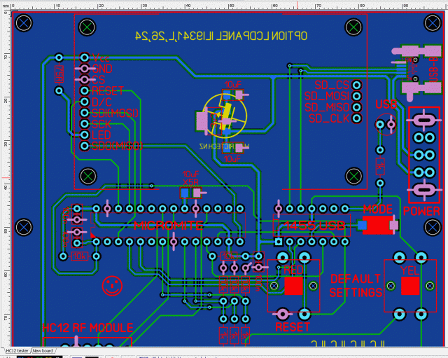
The one thing I noticed looking at the images is the GND and CS pins appear to be connected to a copper pour. Is that section of copper pour truly grounded? --Curtis I am not a Mad Scientist... It makes me happy inventing new ways to take over the world!! |
||||
bigmik Guru Joined: 20/06/2011 Location: AustraliaPosts: 2870 |
GDay Grogster, All, Check that the TFT GND pin is actually connected to GND, by adding the switch you ‘may’ have an isolated GND pour meaning that GND on the TFT is at actually system GND. It is hard to follow the traces with the colour choices but it is basically the same as the original except for the switch and different HC12 layout. Kind Regards, Mick (the big one) . Mick's uMite Stuff can be found >>> HERE (Kindly hosted by Dontronics) <<< |
||||
Grogster Admin Group Joined: 31/12/2012 Location: New ZealandPosts: 9066 |
Good point, but yes - the LCD GND and the CS pin are connected to the common ground.  Once I unearth my DSO next week, I will try to get a screenshot of the D/C line that Jim wanted. Smoke makes things work. When the smoke gets out, it stops! |
||||
bigmik Guru Joined: 20/06/2011 Location: AustraliaPosts: 2870 |
Hi Grogster, Looking further it does seem that a GND does connect to the Pic and the TFT but that image above is your old version without the new switch. This is a curious issue. Suggestions are to minimise it by removing sections you don’t need (like the SD connector and any HC12) Not much to minimise though. Are you able to post images of top and bottom copper without the copper pours and individual copper layers (with pours) and without the other layer showing? That would make tracing the wiring easier. Regards, Mick . Edited 2024-04-21 11:01 by bigmik Mick's uMite Stuff can be found >>> HERE (Kindly hosted by Dontronics) <<< |
||||
bigmik Guru Joined: 20/06/2011 Location: AustraliaPosts: 2870 |
Grogster, Another thought. Are the 2 capacitors on the VReg actually 10uF? You may have accidentally used 10nf maybe? I can’t see any logical reason for one board to work and the other not to. Mick Mick's uMite Stuff can be found >>> HERE (Kindly hosted by Dontronics) <<< |
||||
| Turbo46 Guru Joined: 24/12/2017 Location: AustraliaPosts: 1593 |
I did ask about the capacitor and Grogster said it was OK. The PIC does run and drive the LEDs but I guess it could be marginal? Could be worth trying another. Bill Keep safe. Live long and prosper. |
||||
| Mixtel90 Guru Joined: 05/10/2019 Location: United KingdomPosts: 5735 |
The regulator pads look right for the SOT-223 package. I hope that's the one used here as the SOT-89 is different. Mick Zilog Inside! nascom.info for Nascom & Gemini Preliminary MMBasic docs & my PCB designs |
||||
Grogster Admin Group Joined: 31/12/2012 Location: New ZealandPosts: 9066 |
Yes, SOT-223.  I'll upload the images Mick asked for later, but have some other work to do today, so that will be later on tonight my time. Smoke makes things work. When the smoke gets out, it stops! |
||||
| zeitfest Guru Joined: 31/07/2019 Location: AustraliaPosts: 386 |
Any resolution ? Without a deep dive my only thought is that the blue pour connections running between the 170 pins seem thin, maybe one is intermittent or high resistance. Displays can be a pain. (ed - what size is the display ? I got the impression it was 2.2 ? As it happens I have a similar display (2.2") that works OK but the controller is ILI9225.) Edited 2024-04-26 11:46 by zeitfest |
||||
Grogster Admin Group Joined: 31/12/2012 Location: New ZealandPosts: 9066 |
No, and as it is relatively low-priority compared to other paid work I needed to get done, it has basically just sat on the bench for the last few days.  I have not forgotten it though, and will get back to it when I can - which should be sometime next week when I expect to have a little more time to tinker. LCD is an ILI9341, 2.2" without touch. Smoke makes things work. When the smoke gets out, it stops! |
||||