
|
|
Forum Index : Electronics : Wiseguy (WG) Inverter Build Discussions Australia
| Author | Message | ||||
| KeepIS Guru Joined: 13/10/2014 Location: AustraliaPosts: 2177 |
You simply measure each winding, they should be the same looking at the choke, and treat it as dual chokes, design idea I believe was to help reduce more of the 23kHz PWM and harmonics in the toroid. The harmonic distortion is extremely low in my inverter using dual Sendust toroid stack chokes, and they have "very high" saturation levels. If you make a tester, measure one half, double the value and let us know the total saturation level. NANO:Inverter V 8.2ks - Linux AvrDude GUI script V4.1 |
||||
| phil99 Guru Joined: 11/02/2018 Location: AustraliaPosts: 3293 |
As they are on a single core they are really a single inductor. The Amp-Turns of the two windings will add so the total saturation current will be half that of a single winding. The total inductance will be 4 times that of a single winding as L is proportional to N(total)^2 on a single core. Edited 2026-06-07 12:18 by phil99 |
||||
Bryan1 Guru Joined: 22/02/2006 Location: AustraliaPosts: 2099 |
With this dual choke each side is phased so would hooking them up as a pair distort the readings. |
||||
| KeepIS Guru Joined: 13/10/2014 Location: AustraliaPosts: 2177 |
@phil99, didn't see your first post, it will be interesting to see the difference in testing, however that would make the choke far less desirable in an inverter. It's worth remembering that early Inverters were running ferrite E-Cores with very low saturation levels, and these still allowed "SOME" Inverters builds to start huge loads, but that depended on build quality, cable - size - terminations - length, Toroid parameters, Mains wiring interface, fuse losses and filters etc, and for many builds, they were still a blowup waiting to happen. Except for pure Resistive loads, Inverters draw very high DC peak surge current, these can be are far in excess of apparent loads ratings. A BIG Sendust core, or smaller stacked Sendust cores, will usually provide the highest saturation safety when built correctly. NANO:Inverter V 8.2ks - Linux AvrDude GUI script V4.1 |
||||
| phil99 Guru Joined: 11/02/2018 Location: AustraliaPosts: 3293 |
They are already "hooked up as a pair" by the single core. With two windings it isn't just an inductor, it is also a transformer. The magnetic flux of each winding is coupled to the other winding by the core. That depends on the number of turns and the cross-section of the core. If the total inductance (both windings in series) is higher than necessary the number of turns can be reduced. That will reduce the flux density and raise the saturation current. If the core has gaps they will produce a softer saturation curve. The core looks like Grain-Oriented Silicon Steel so I expect it will have gaps as without them GOSS has a hard saturation curve, though at quite a high flux density compared to other materials. Without gaps, for maximum FET safety the cross-section would need be similar to the transformer core. Saturation and inductance testing will reveal all. |
||||
disco4now Guru Joined: 18/12/2014 Location: AustraliaPosts: 1127 |
This is the big aerosharp choke I used. I could only get 9 turns each side and increased the gap to 4mm. I tested as a single choke with the transformer end shorted. 5 turns each side @ 1.6mm gap gave 51uF saturation 180-190 amps 9 turns each side @ 4.0mm gap gave 55uF(45uF) saturation 300-350 amps I did it some time ago, I think inductance might have dropped to about 45uF when wound with the bigger cable. I have not tested with a big inductive load yet, but it does start a bunnings 1250 watt wet/dry vacuum cleaner without a blow up. 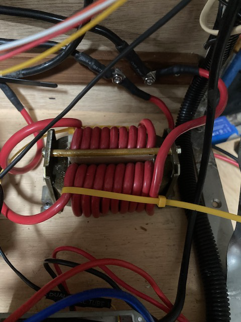 F4 H7FotSF4xGT |
||||
| KeepIS Guru Joined: 13/10/2014 Location: AustraliaPosts: 2177 |
Obviously, as it does for any core, however I doubt it will come anywhere near the minimum 350A needed, and for a 6kW/25kW LF Inverter, at least 500A saturation would be desirable. @disco4now, that is interesting, if those figures are accurate then, it might be ok, how hot would it run at around 5kW for an hour. FYI a big wet dry vac from bunnings peaks at 236A on start, two plug-packs for the new Desktop monitors hit 300A to 350A at morning power on. . Edited 2026-06-07 15:03 by KeepIS Footnote added 2026-06-08 08:51 by KeepIS The currents above are DC input currents. NANO:Inverter V 8.2ks - Linux AvrDude GUI script V4.1 |
||||
| phil99 Guru Joined: 11/02/2018 Location: AustraliaPosts: 3293 |
The surge current of that is very high but the PF will also be fairly high as it has a brush type motor. Most of that current is providing "real" power accelerating the armature and impeller. The low PF of an induction motor at startup is a bigger problem as the voltage and current waveforms are way out of sync. In addition to the high power needed for acceleration up to 2/3 of the current drawn from the inverter on one quarter cycle is pushed back through the inverter on the next. |
||||
| Bryan1 Guru Joined: 22/02/2006 Location: AustraliaPosts: 2099 |
Well Guy's I am having a bit of fun playing with Sprint Layout and in time I will come up with a new PCB design that uses the 5 off 450 volt 560uf caps off the aerosharp board and as I do have 6 off 35 volt 10000uf caps they will be used too. Now I'm using the schematic to work off and noticed the nano doesn't have a connection for the Vin so that will need to be sorted. I don't have any BNC to BNC cables and most won't either so for the scope inputs pins can be used with earth pins put in for using the probes. As my software is new I have to make macros for just about everything so that is taking time so I will get there. Regards Bryan |
||||
| Bryan1 Guru Joined: 22/02/2006 Location: AustraliaPosts: 2099 |
Ok nearly time to call it a day and got the basic design done just need to check the sizes of some components etc and sort the Vin for the Nano. 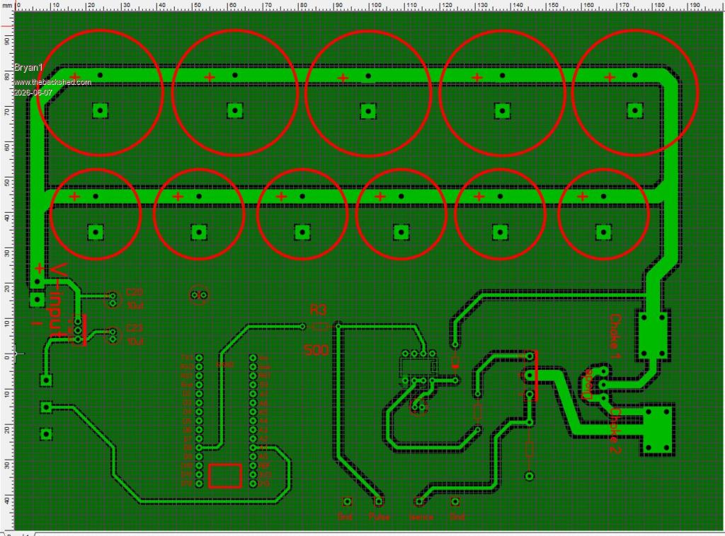 Regards Bryan Edited 2026-06-07 17:38 by Bryan1 |
||||
| Bryan1 Guru Joined: 22/02/2006 Location: AustraliaPosts: 2099 |
Well silly me should of realized the nano will be connected by USB so the computer can read the serial in. |
||||
| Bryan1 Guru Joined: 22/02/2006 Location: AustraliaPosts: 2099 |
Ok had another look this morning and fixed a few things, now with the 0.02 ohm resistor I found some on Ali so 20 of them are on the way  Here is a picture of the positive rail 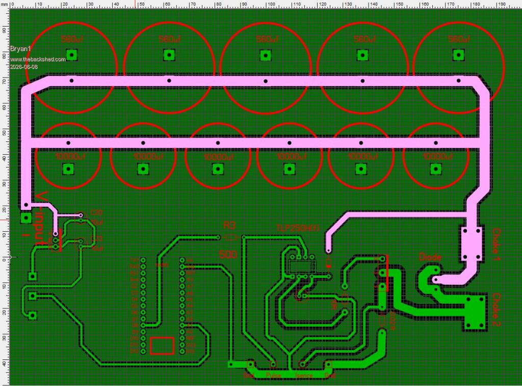 Here is the negative rail 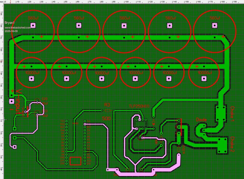 Now the board has passed the DRC test so I do think I have everything right so today I'll upload the board to JLCPCB and get 5 boards made to get started so if any problems arise a V2 board can be made.Regards Bryan |
||||
| Bryan1 Guru Joined: 22/02/2006 Location: AustraliaPosts: 2099 |
Ok got the order with JLCPCB all done and $27.65 the cost, now as the board is 200x150 it has bumped the price up from my last orders of $3.50  So the waiting game has started again..... |
||||
| BarryH Regular Member Joined: 05/01/2025 Location: AustraliaPosts: 45 |
Hi Bryan. I'm just learning to do some of my own PCBs. What is the advantage of having the negative tracks over just using the copper ground plane and using thermal pads? BarryH |
||||
| Bryan1 Guru Joined: 22/02/2006 Location: AustraliaPosts: 2099 |
Well Barry Mixtel put me onto doing the ground plains and he IS the guru of Sprint Layout. I was surprised I could get the circuit on the one layer, now with my first upload which did fail and I'm glad it did as I only had 1.5mm holes for the snapin caps so I opened the holes out to 2mm and uploaded the zip file where it went thru As I had used Sprint Layout before relearning has been pretty easy and with this board first measuring with my dial vernier to get the distance then using the measure tool make the pads to suit. Then finish off the part and select it all then save as Macros so it's there for future use. Regards Bryan |
||||
| nickskethisniks Guru Joined: 17/10/2017 Location: BelgiumPosts: 477 |
It's not completely clear to me but connect your power ground/negative rail plane and digital ground in 1 point. It looks like you have 1 plane for the 2. You can have a positive power plane too instead of a single track so it acts like a laminated bus. Have some inspiration from solar mike his posted design. That is how I would do it. Edited 2026-06-09 00:03 by nickskethisniks |
||||
| KeepIS Guru Joined: 13/10/2014 Location: AustraliaPosts: 2177 |
Re-posted here in case someone is interested: For anyone looking for a small 0-60V 0-5A supply for safely testing the Nano inverter, the following is around $100 AU, free shipping, the model you want is 605. Link to model 605 60V 5A supply NANO:Inverter V 8.2ks - Linux AvrDude GUI script V4.1 |
||||
| nickskethisniks Guru Joined: 17/10/2017 Location: BelgiumPosts: 477 |
Are these the correct beads: (I was thinking they should be the same as FX1115) TUB4/2/5-3B1 https://www.digikey.be/nl/products/detail/ferroxcube/TUB4-2-5-3B1/21689331?s=N4IgTCBcDaICoFUBCAWA9GNBWAtAZiQEYQBdAXyA Edited 2026-06-10 22:17 by nickskethisniks |
||||
| Murphy's friend Guru Joined: 04/10/2019 Location: AustraliaPosts: 678 |
Thanks Mike, this is just what I was looking for. Have ordered one  |
||||
| The Back Shed's forum code is written, and hosted, in Australia. | © JAQ Software 2026 |
