Notice. New forum software under development. It's going to miss a few functions and look a bit ugly for a while, but I'm working on it full time now as the old forum was too unstable. Couple days, all good. If you notice any issues, please contact me.
Forum Index : Electronics : Build a Multi Phase PV Charger and 230Vac Inverter Using Pi Pico
Author
Message
Solar Mike Guru Joined: 08/02/2015 Location: New ZealandPosts: 1214
Posted: 03:08am 18 Jun 2026
Copy link to clipboard
Print this post
Now that the PI PICO 2 controller is out and readily available here in NZ at reasonable prices, though I would make a start at moving various projects over to it. As my projects have gotten more complex, the old Picaxe CPU's I have used in the past are proving just too slow and lacking in many features of a modern inexpensive 32 bit processor.
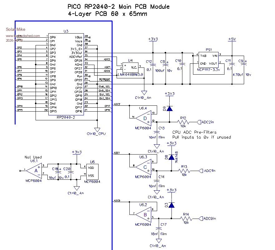
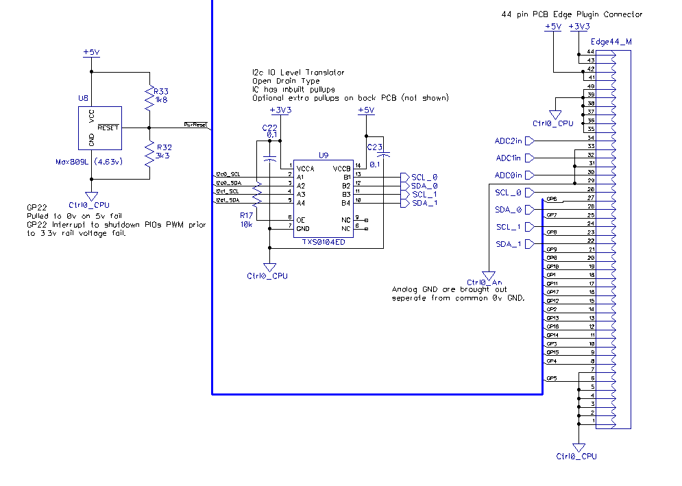
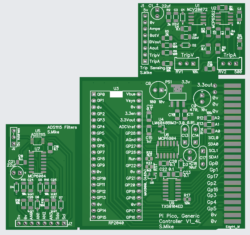
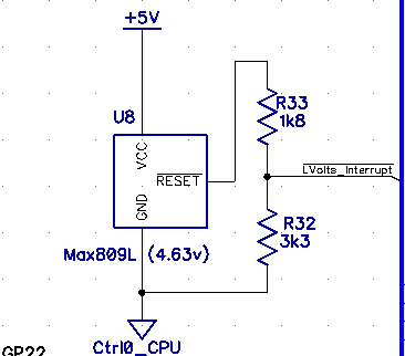
First project is a 3 phase PV charge controller; the Pico-2 PIO can easily be setup to output 3 PWM phases each running at 125 KHz and driving a buck inverter stage. To that end I want a generic plugin PCB module containing the main CPU and some ancillary components, running off a linear 3.3v psu and ADC reference of 3.0v. Included on the pcb is a voltage rail fail reset chip an MAX809L, this resets low at 4.63v, connected to the incoming 5v power it can cause a interrupt on an input pin and allow the cpu to turn off PIO output pwm signals, shutting down cleanly.
Have built this on a small 65x60mm 4-layer pcb with a 44 pin edge connector, so can be plugged in to the main PV host controller. The 4 layers give excellent internal ground and power planes which will help in a noisy inverter environment
Schematic:
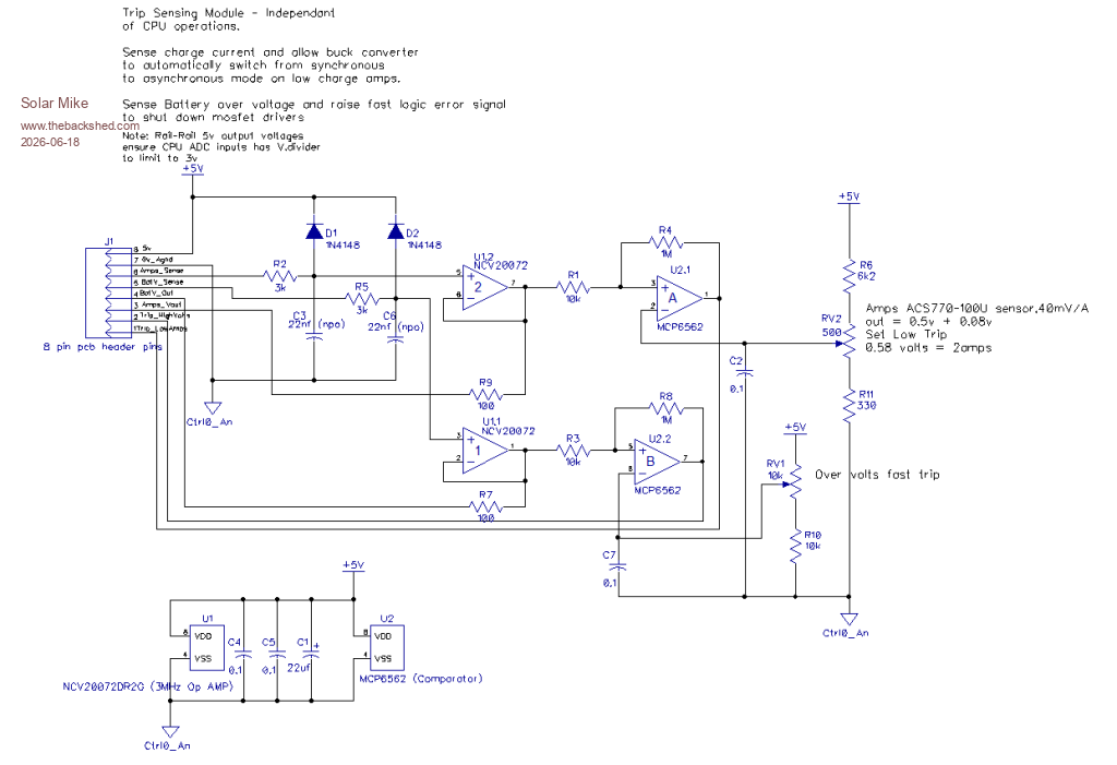
Have also made a couple of small ancillary helper modules with pin headers. These are on the same 100x100mm pcb and cut off. 1: Trip sensing, this pcb has an over voltage detection comparator to allow shut down of the buck inverters independent of the cpu; as if the output fuse blows or battery gets suddenly disconnected the cpu sensing battery voltage cannot react fast enough to prevent the buck output voltage rising to alarming levels and perhaps destroy components.
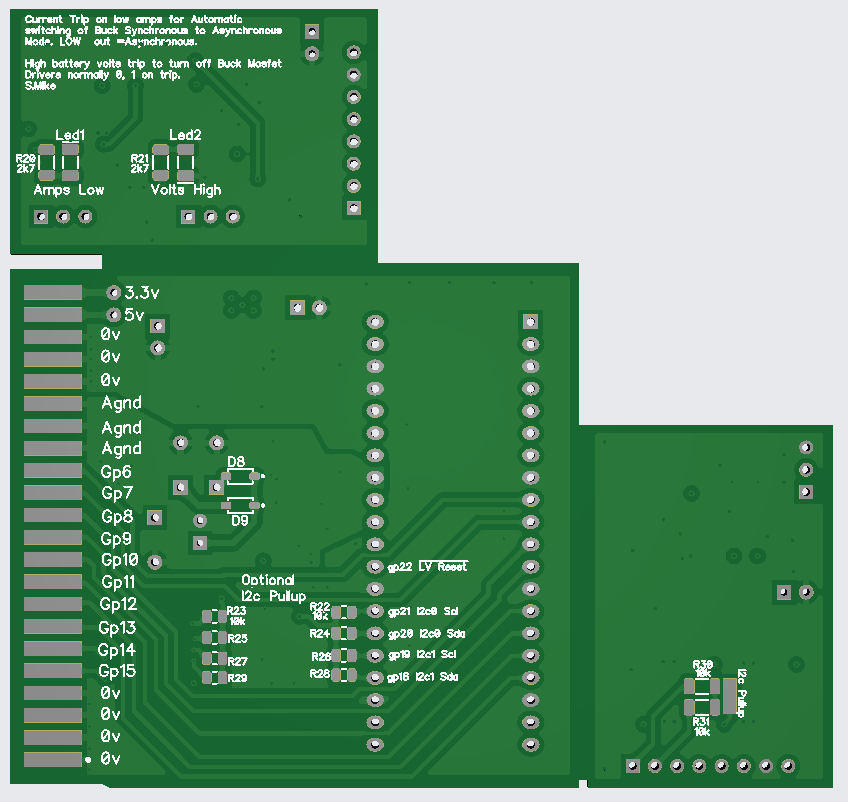
2: Low buck current sense, at very low duty cycles its possible for the buck stages act as voltage boosters, feeding battery power backwards causing high voltages on the main capacitors, again blowing things up. To prevent this I switch off the low side synchronous rectifier mosfets at low current levels, thus turning into asynchronous rectification using the mosfets source-drain diode. CPU has no involvement here, buck stage seamlessly switches between the two modes.
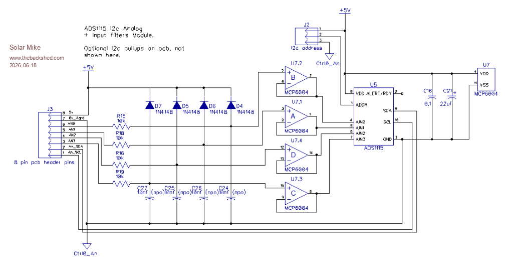
The other helper pcb has a I2c ADS1115 mux analog ADC chip and some high input impedance noise filters, again with 8 pin header, main CPU can use this to get accurate voltage measurements, as the PICO-2 still has a slightly compromised ADC input system.
100 x 100 pcb: to cut up at marked edges:
I quite like Micro Python as an object programming language, so will use that for future work using these boards, its also quite fast and allows access to the 2nd CPU, noted with strict limits. Once I have the main CPU board working, will think about the multi-phase buck design, followed by a 230Vac inverter.
Edit: just noticed an error on the Max809, will fix it. This is how its meant to be wired, OK on the pcb...
Cheers Mike Edited 2026-06-18 13:25 by Solar Mike
Revlac Guru Joined: 31/12/2016 Location: AustraliaPosts: 1277
Posted: 12:08am 19 Jun 2026
Copy link to clipboard
Print this post
This is very interesting, I don't think I have seen any standalone chargers like it, I may have some questions later. Will be watching.Cheers Aaron Off The Grid
Solar Mike Guru Joined: 08/02/2015 Location: New ZealandPosts: 1214
Posted: 02:19am 19 Jun 2026
Copy link to clipboard
Print this post
I have made 2 phase chargers in the past, using many RC + schmitt trigger delay stages in series, then tapping off at the correct delay point; but its messy and limited to range of pwm duty values; much easier using the Pico 2 module.
Using 3 smaller buck inductors is a lot easier to make also, that and the combined output ripple frequency of 3 x the pwm put a lot less stress on components.
Cheers Mike
Solar Mike Guru Joined: 08/02/2015 Location: New ZealandPosts: 1214
Posted: 11:34am 21 Jun 2026
Copy link to clipboard
Print this post
Making a start on this project with the buck inverter modules; each buck output phase will be a 100 x 100mm pcb with bus bar connections to the other 2 phases for PV volts, 0v common and battery output.
Will use two TO-247 mosfets on each module mounted under the pcb, so they are pressed against a heat sink - 3mm thick alloy plate - bottom of case or box. To get best gate driver connections its easier to mount the driver components on a separate pcb that solders direct on top of the mosfet pins. Then link these to the PICO controller via 10 pin IDC cables.
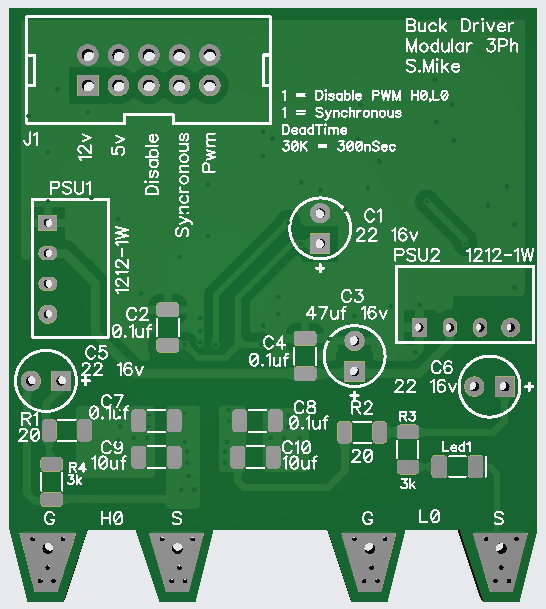
Here is a test build of the driver module, they are quite small, 4 will fit on a 100x100 pcb.
Top:
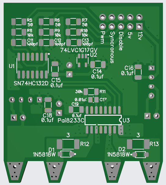
Bottom:
Concept is quite straight forward, all inputs are high freq filtered then into schmitt trigger NAND gates, the Synchronous signal allows turning off the L0 input during low duty cycles to prevent the buck stage turning into a voltage power booster - Not good, the Disable input via schmitt buffer, turns off the mosfet driver PAI8233c, these are 4 amp fully isolated drivers with resistor set dead time. Small 1w 12-12v psu's provide isolated mosfet bias, note they require min load current (3k Resistor) on output. The main PICO board will turn off the input 12v supply to the 2 PSU's under no charge conditions.
I haven't created a schematic for these yet, back of a napkin scribble is all there is currently; and it may not be the final version.


 I don't think I have seen any standalone chargers like it, I may have some questions later.