| Author |
Message |
jakesea
Newbie

Joined: 30/09/2023
Location: United KingdomPosts: 8 |
| Posted: 02:50pm 24 Apr 2024 |
 Copy link to clipboard Copy link to clipboard |
 Print this post |
|
Hi, my name is Jake and I live in the UK. It is my first post so be easy on me, please.
I purchased the Ozinverter book and pcb boards from Clockmanfr and tried to follow the manual to the best of my ability. Apparently not good enough and unfortunately, it isn't going as expected. It simply blew up 3 times now...
First time, I suspect, my start up was not correct and quite a few of the mosfets went with a big bang. I re-soldered them all, put a new EG8010 chip, checked what I was able to and tried again. The same result. Changed them all again, read about the subject, read the manual again, checked what I knew and connected it all again and it blew up again although the last time it was not as instant as the first two times and now I cannot even see what went off because all the mosfets look ok physicaly.
At the moment, I am out of my depth.
Would you be willing to help me out in finding out what is wrong with my build, please?
I could provide more info, photos etc.
Where should I start?
Thanks
Btw. is it still the case that only particular EG8010 chips should be used or it does not matter any more? (I have just read about it today) I couldn't find them on ali or ebay. |
| |
mab1
Senior Member

Joined: 10/02/2015
Location: United KingdomPosts: 165 |
| Posted: 03:40pm 24 Apr 2024 |
Copy link to clipboard |
Print this post |
|
Hi jake,
Ok, first question:
what test equipment do you have (multimeter? Oscilloscope? Bench powersupply? Lamp and wire?).
2. How much electrical or electronic testing experience do you have (bit of a vague question i know, but give us an idea)?
3. I assume you have either bought or built a transformer, an inductor, and of course the powerboards from clockman; what testing have you done on each of those individually before assembly and connecting the battery? |
| |
jakesea
Newbie
Joined: 30/09/2023
Location: United KingdomPosts: 8 |
| Posted: 04:16pm 24 Apr 2024 |
Copy link to clipboard |
Print this post |
|
Hi mab1,
thanks a lot for responding to my cry for help...
yes, i have multimeter, osciloscope (small, cheapo one but shows waves), bench power supply and soldering equipment
not much experience in electronic testing but I would imagine I know a little bit about electronics in general - some basics
yes, I have built the transformer myself following the manual. An inductor? Do you mean the one on the transformer? I have this one as well.
I checked every single component for the right values. Mosfets: checked them with the small tester to check if they have similar values but I did not test if they were correct - I didn't know how. I assumed that if 24 fets had similar values the chances were they were correct.
Thats all the testing I had done before I connected it the first time.
The last time I did some reading about the EG8010 chip and the board so checked for correct voltages from driver transistors and checked the spwm out on the chip
I think it would be it
Edited 2024-04-25 02:18 by jakesea |
| |
mab1
Senior Member
Joined: 10/02/2015
Location: United KingdomPosts: 165 |
| Posted: 09:21pm 24 Apr 2024 |
Copy link to clipboard |
Print this post |
|
Ok, i haven't yet built an inverter so my ability to help may be limited. Hopefully someone who's built an ozinverter will come along and make more informed suggestions. I'm sort of assuming that the power stages are similar to the Chinese egs002 based boards (because i can't remember what i read about the ozinverter - it's been too long).
But I'm just trying to narrow the possibilities of where the issue lies, so sorry in advance if i ask what seems a really obvious thing - i prefer to start with the absolute basics rather than assume something has been checked:-
I assume when testing by connecting to the mains, the quiescent current of the transformer was reasonable?
The inductor is around 50(?)uH have you verified that?
Before power up have you verified all the mosfet gates are neither shorted to source / drain, nor left floating unconnected to the drivers.
Before switch on, have you verified that all the h-bridge mosfets are not shorted (i.e. no shorts between transformer outputs and power rails)
When you try and start it up, what do you actually do (your start up sequence)? and how far does it get before it goes bang?
With the power board supplied from a current limited supply, does the 8010 allow you to 'scope the pwm outputs with the tranny disconnected? (Or does it shut down because it's not seeing the expected output)? If it does run long enough, are the 'scope traces as expected?
Edited 2024-04-25 07:23 by mab1 |
| |
KeepIS

Guru

Joined: 13/10/2014
Location: AustraliaPosts: 1372 |
| Posted: 10:26pm 24 Apr 2024 |
Copy link to clipboard |
Print this post |
|
You should have started the inverter first time with no main capacitors.
It should have had around a 10watt 47ohm resistor in series with the supply (or a current limited supply)
If you fit the Caps and try to test it, it will likely cause a blowup if something is wrong when it starts.
WHY? Because a bank of charged Capacitors will/can destroy an inverter if the fault only appears under start or running conditions.
That means that once the caps are charged, the current limited supply is rendered useless, the series 47 ohm resistor is rendered useless, neither can protect the FETs if you have something amiss in wiring or SPWM drive with a bank of charged capacitors. Charged Caps = sticks of FET dynamite.
.
Edited 2024-04-25 11:09 by KeepIS
It's all too hard.
Mike. |
| |
oh3gdo
Regular Member

Joined: 18/11/2021
Location: FinlandPosts: 42 |
| Posted: 05:20am 25 Apr 2024 |
Copy link to clipboard |
Print this post |
|
jakesea
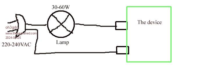
I do not know how your Ozinverter works, but i think it works with 220-240VC,
To limit the current, you must limit the voltage.
How much?
I do not know, but if you put normal or led lamp with the series of power, it doesn't burn the whole device.
Then when the lamp is lighting start to measure all power supply circuits.
The voltages are much smaller than normally, but is something 0V?
I have designed electronics devices from 860kV to chips more than 50 years
Pekka Ritamaki |
| |
KeepIS
Guru
Joined: 13/10/2014
Location: AustraliaPosts: 1372 |
| Posted: 05:52am 25 Apr 2024 |
Copy link to clipboard |
Print this post |
|
Not if you have 10,000uf or more of capacitance that may be charged up to 50v on the Inverter board, and sitting directly across the FETS.
In a new untested build, if the inverter has a drive problem or a configuration problem - it can blow FETs.
The Globe, the 10w Resistors, the regulated supply, all will only work for shorts or high current IF the inverter starts as a very low voltage - if it charges the caps before starting - it can destroy the FETs or other components.
This often happens with new builds - remove the caps or keep the voltage below 5V!
It's all too hard.
Mike. |
| |
nickskethisniks
Guru
Joined: 17/10/2017
Location: BelgiumPosts: 416 |
| Posted: 08:54am 25 Apr 2024 |
Copy link to clipboard |
Print this post |
|
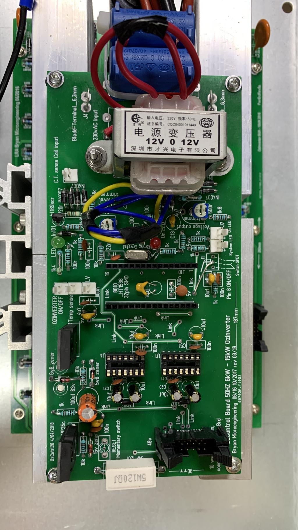
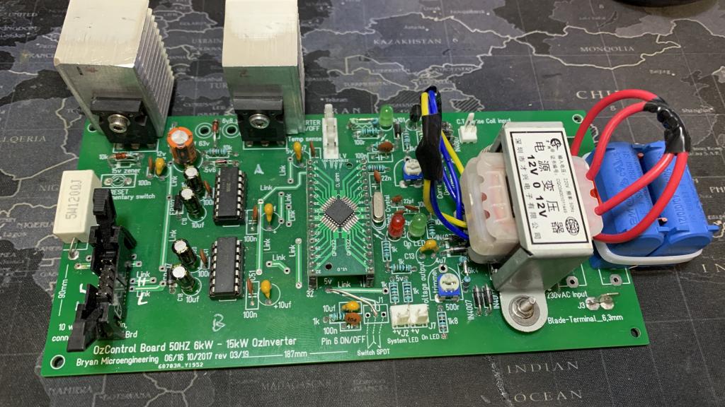
I would start with posting pictures of your pcb's to see the quality of your solderwork.
Second where did you obtain your components from? In my view and others experiences you should not order them directly from china (aliex,....) Farnell, mouser, tme, digikey, etc... are the places to go.
I've build the ozz inverter myself and it's still up after powering up around 5y ago. But all components are genuine.
Only blew 4 MOSFETs and driver because of a short connection when probing with my oscilloscope, but I have a solid electronics background and should have know better.
Start with probing all voltage rails first. Populate only 4 MOSFETs, use a resistor instead of the transformer. That way you can test without blowing things up. After a blow up you can't 100% trust everything with a bit of silicon in.
We will guide you thru the process, I should reread the manual but I thought there was enough guidance in it |
| |
jakesea
Newbie
Joined: 30/09/2023
Location: United KingdomPosts: 8 |
| Posted: 10:14am 25 Apr 2024 |
Copy link to clipboard |
Print this post |
|
Thank you all for your responses
mab1
I assume when testing by connecting to the mains, the quiescent current of the transformer was reasonable?
I checked the voltages (they were as expected ) and I had a lamp connected so I could see it light up - not sure if that it is what you meant
The inductor is around 50(?)uH have you verified that?
No, I haven't. I don't know how. How can I measure it?
Before power up have you verified all the mosfet gates are neither shorted to source / drain, nor left floating unconnected to the drivers.
Yes, visually
Before switch on, have you verified that all the h-bridge mosfets are not shorted (i.e. no shorts between transformer outputs and power rails)
Yes
When you try and start it up, what do you actually do (your start up sequence)? and how far does it get before it goes bang?
I used the over temp method as recommended in the manual: I connected 2 pins for over temp to a main switch which is 'normally close'.
I have connected the battery (48v, LiFePO4, 300Ah) through 2 pole breaker with negative shorted through 47R resistor and momentary switch that i used to precharge caps. When I saw cca. 53v on the dc monitor on inverter I switched the battery breaker on. Then I turned the main (over temp) switch on. Then everything went quiet for some time - no other monitors were on so I thought that the board hung up so I pressed the reset button then there was the first bang and short while later the second one...
With the power board supplied from a current limited supply, does the 8010 allow you to 'scope the pwm outputs with the tranny disconnected? (Or does it shut down because it's not seeing the expected output)? If it does run long enough, are the 'scope traces as expected?
Honestly, I am not sure if I measured it correctly so I will start measuring what I can again and I will report back
KeepIS
You should have started the inverter first time with no main capacitors.
It should have had around a 10watt 47ohm resistor in series with the supply (or a current limited supply)
I will definitely do it exactly as you say next time
This often happens with new builds - remove the caps or keep the voltage below 5V!
I will remove caps- thats for sure - thanks a lot.
oh3gdo
The voltages are much smaller than normally, but is something 0V?
I will start checking and report back - thanks
nickskethisniks
I will post the picures in a moment.
Second where did you obtain your components from? In my view and others experiences you should not order them directly from china (aliex,....) Farnell, mouser, tme, digikey, etc... are the places to go.
Many came from the rs-online.com but eg8010, 24 mosfets and the big caps are from ali.
Start with probing all voltage rails first. Populate only 4 MOSFETs, use a resistor instead of the transformer. That way you can test without blowing things up. After a blow up you can't 100% trust everything with a bit of silicon in.
Ok, I will do that thanks. What kind of resistor would you say I should use? What about ac voltage feedback? Will the control board still work or maybe I could put 12v on the output of the feedback transformer? |
| |
jakesea
Newbie
Joined: 30/09/2023
Location: United KingdomPosts: 8 |
| Posted: 10:48am 25 Apr 2024 |
Copy link to clipboard |
Print this post |
|
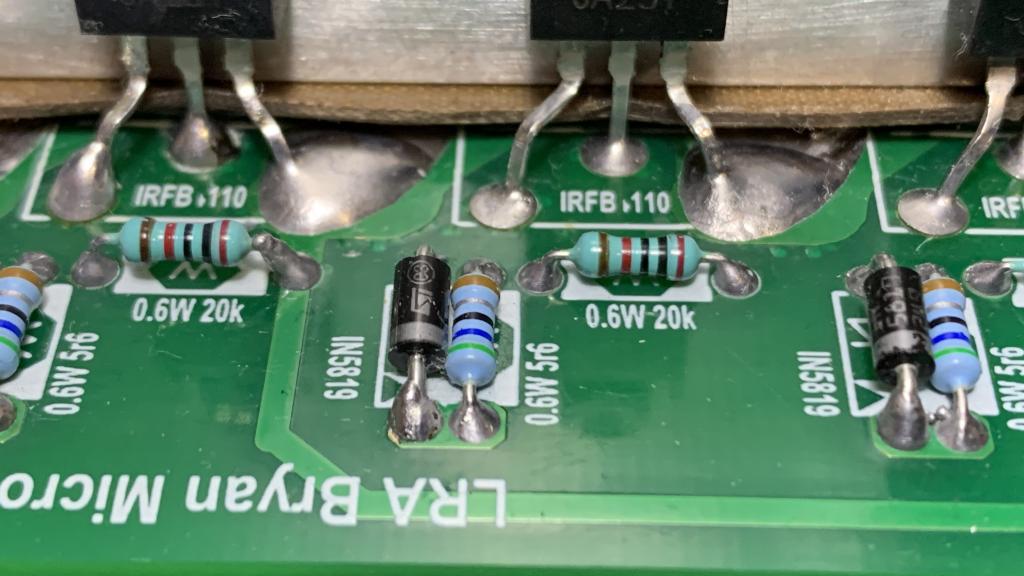
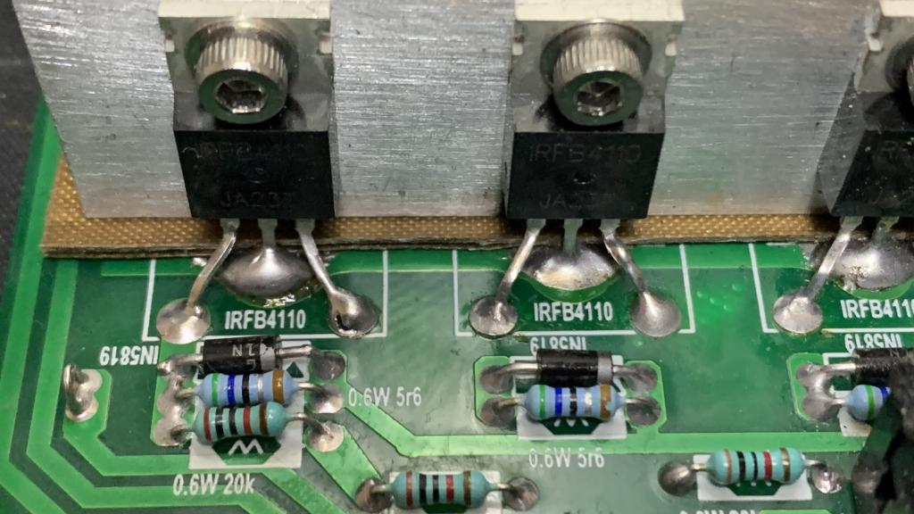
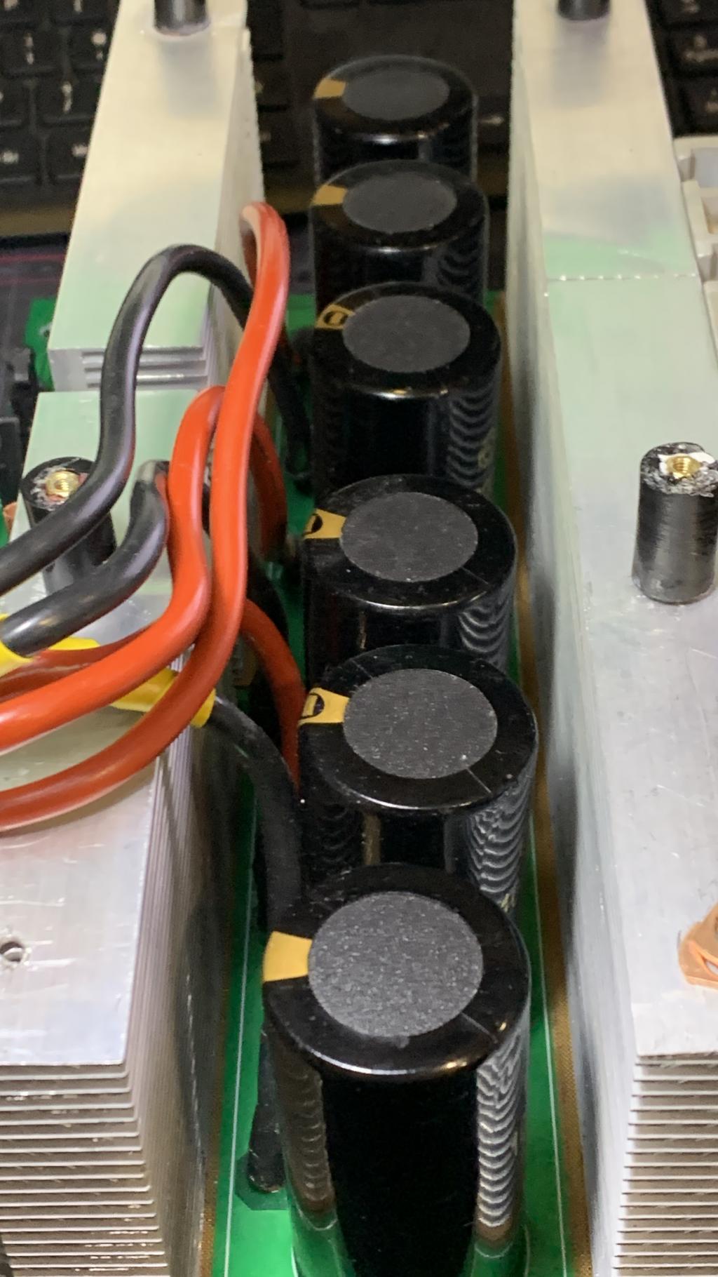
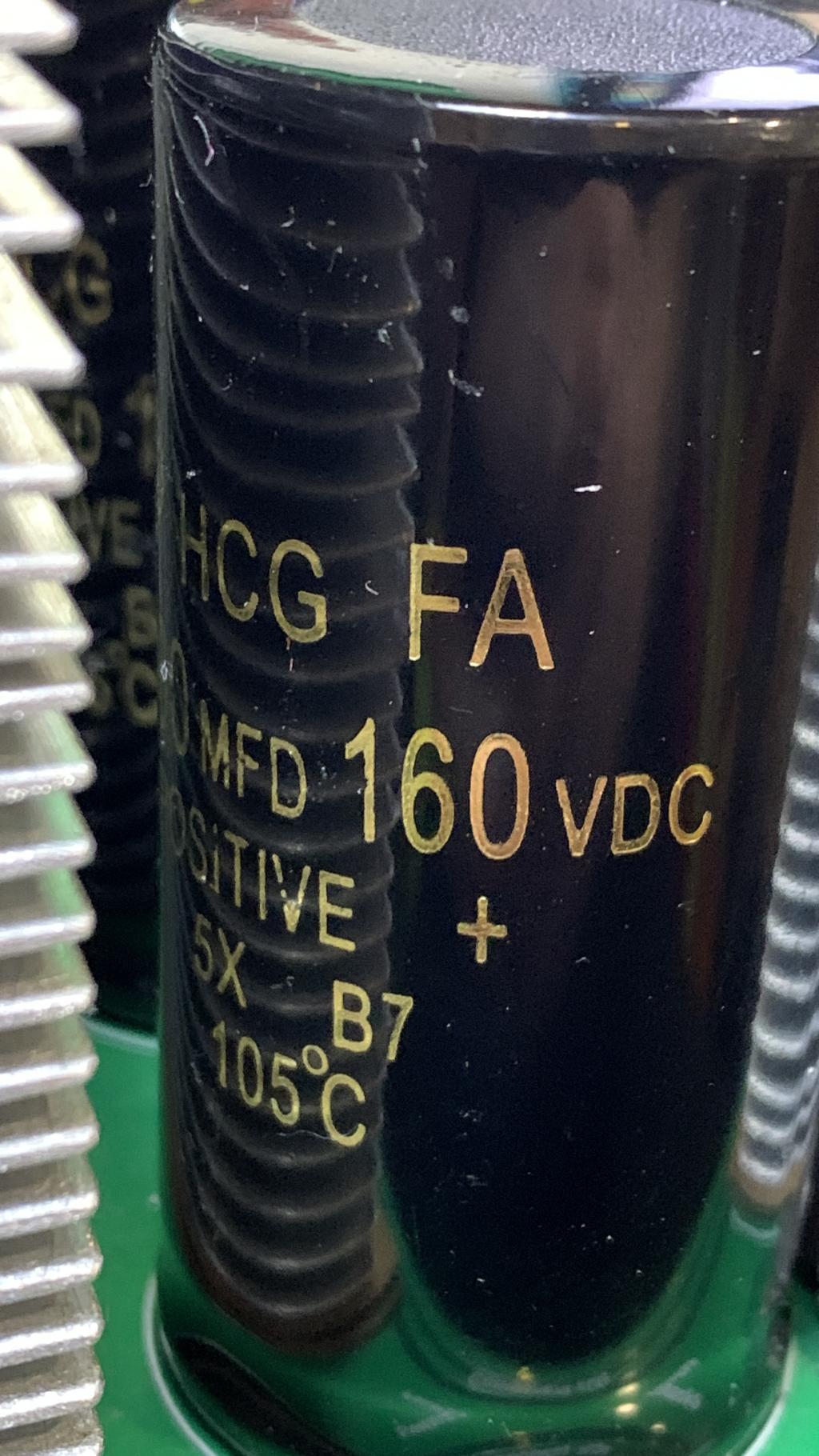
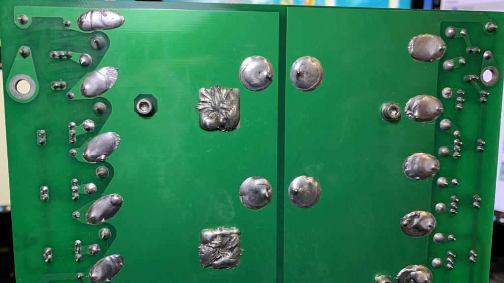
some picures of my build
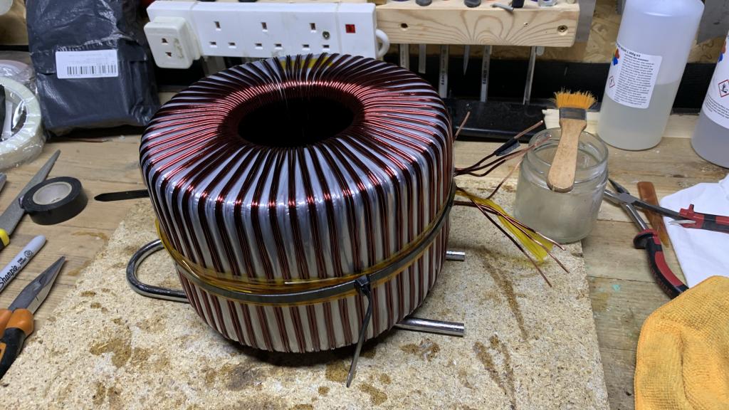
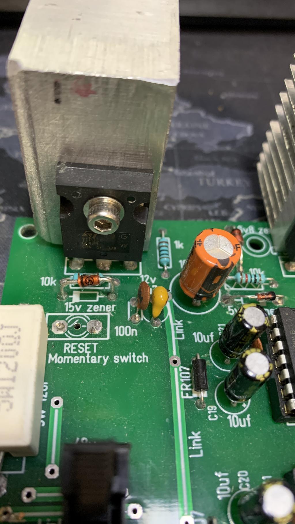
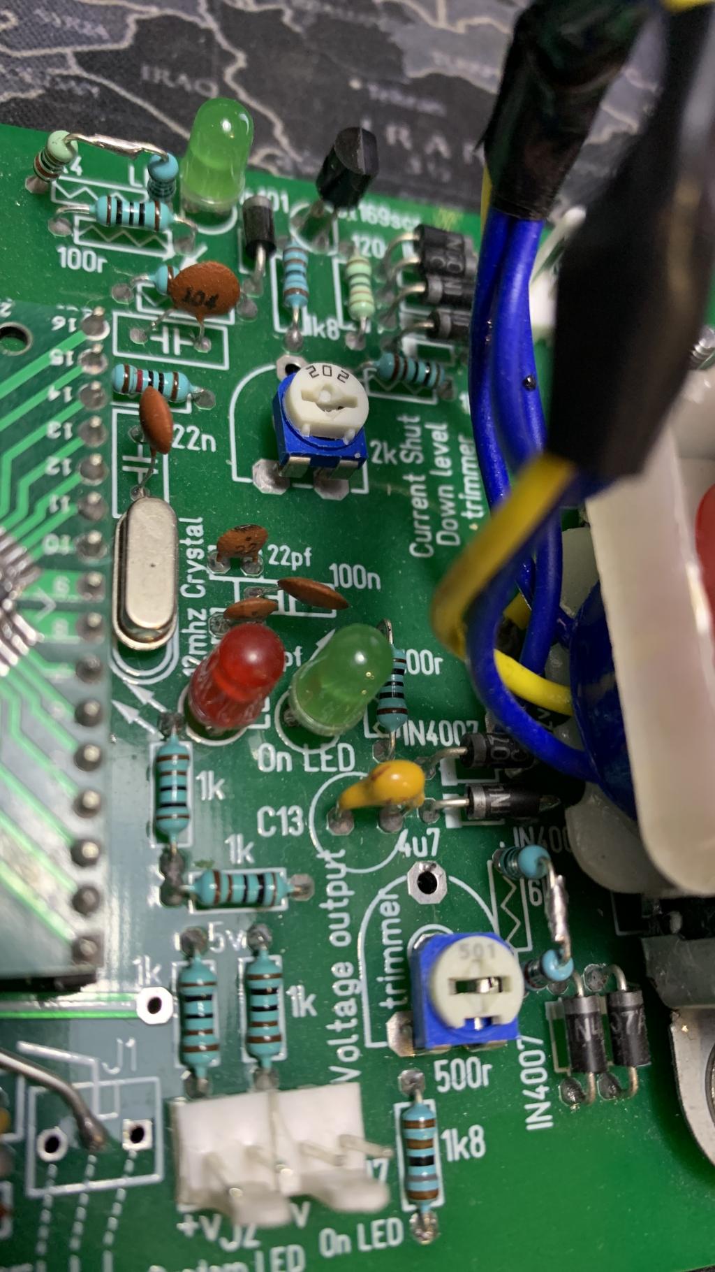
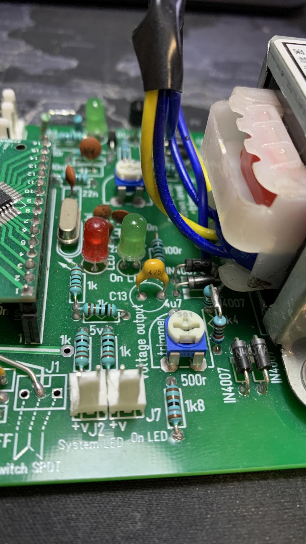
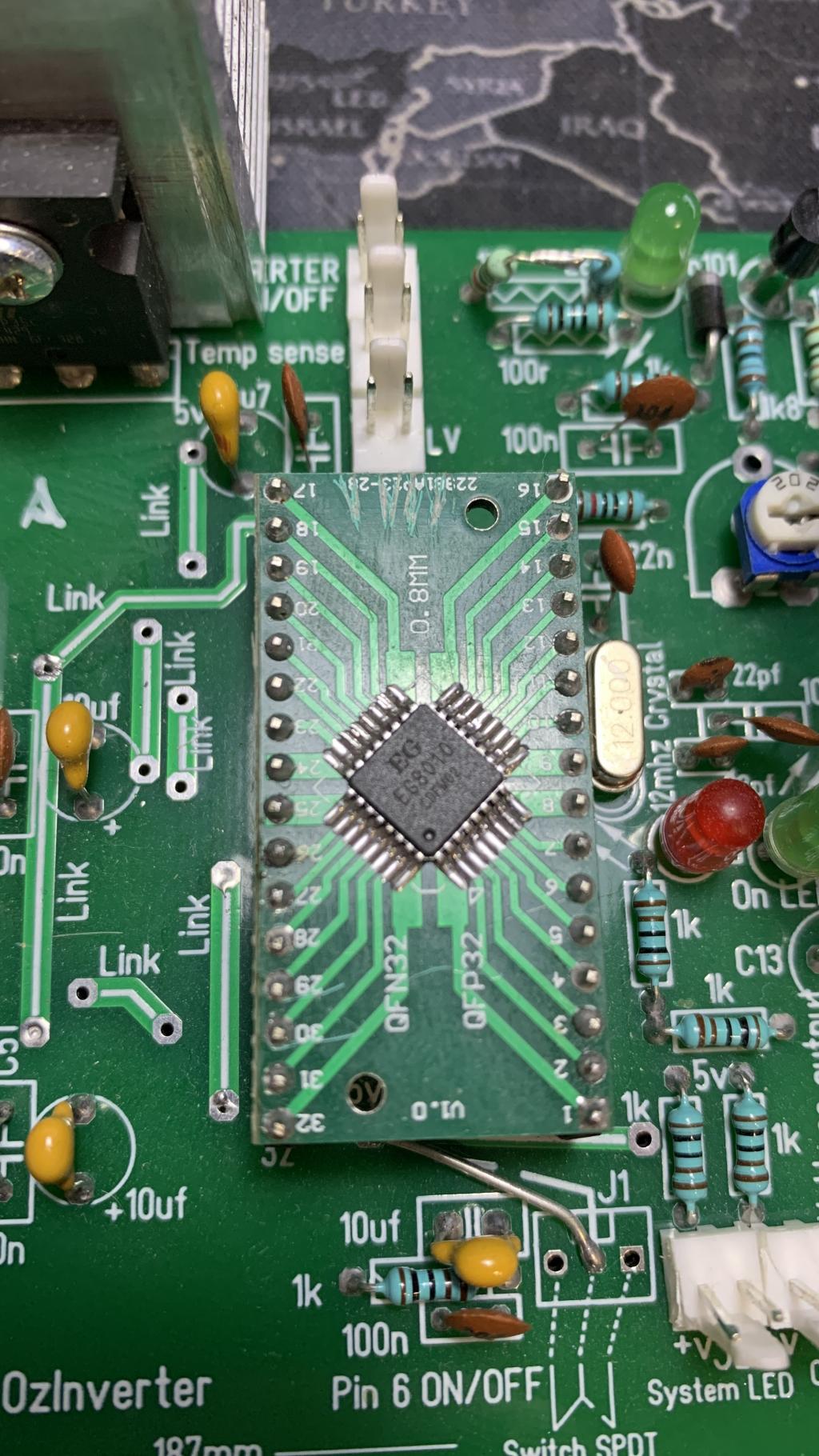
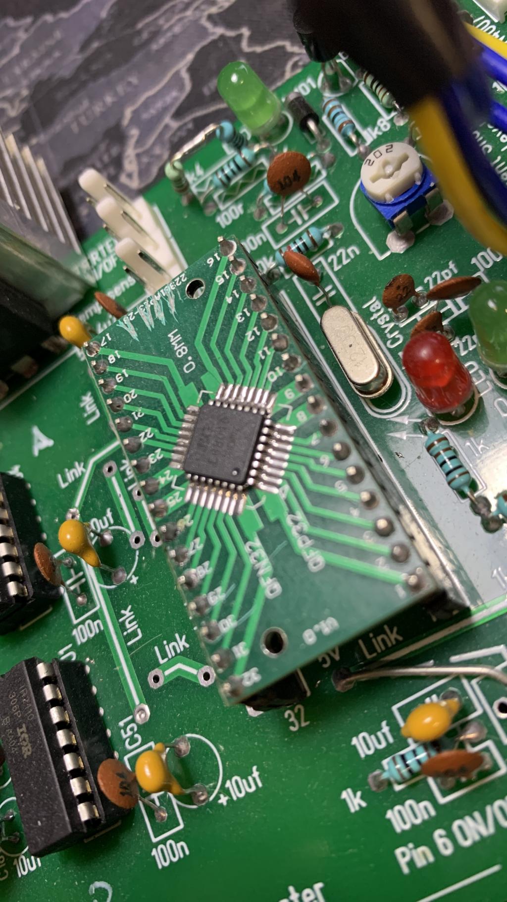
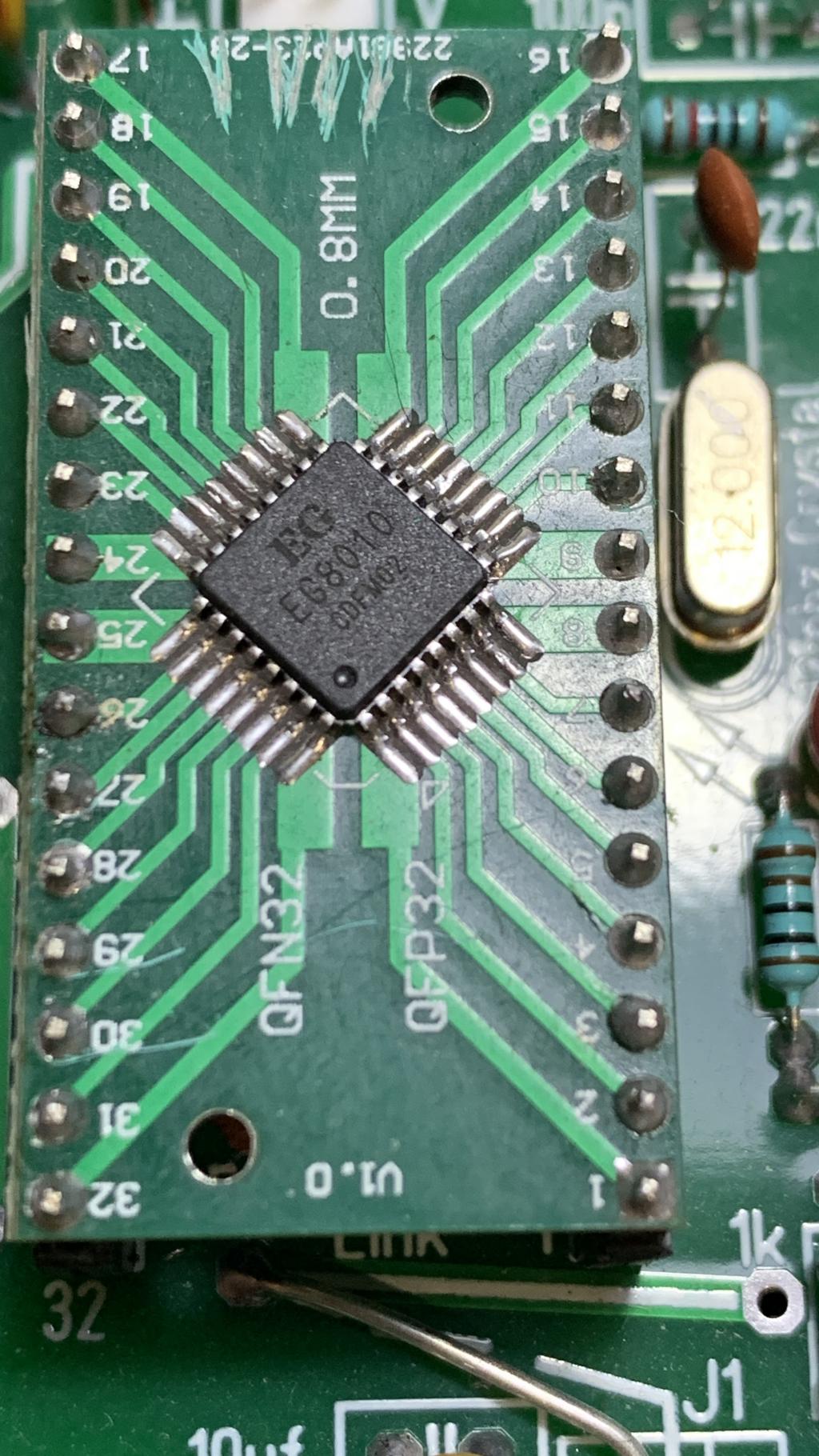
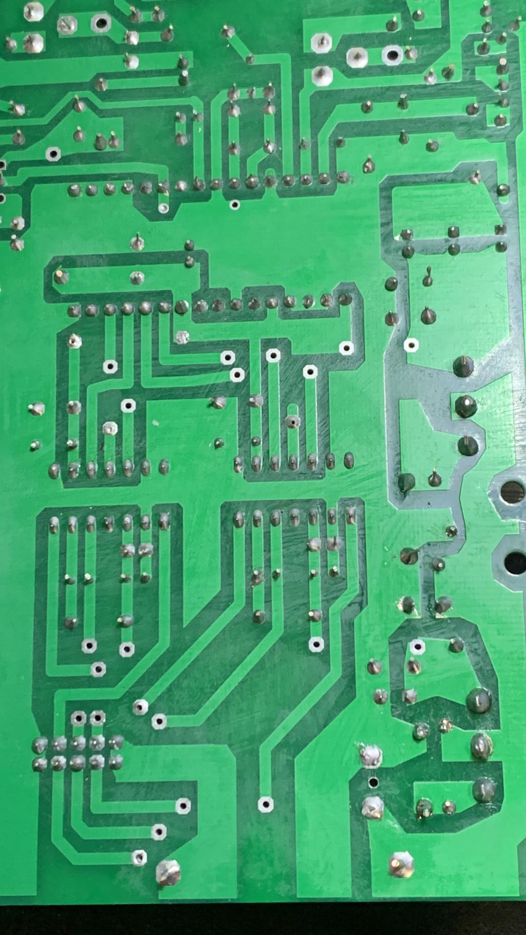
power board to follow |
| |
jakesea
Newbie
Joined: 30/09/2023
Location: United KingdomPosts: 8 |
| Posted: 11:08am 25 Apr 2024 |
Copy link to clipboard |
Print this post |
|
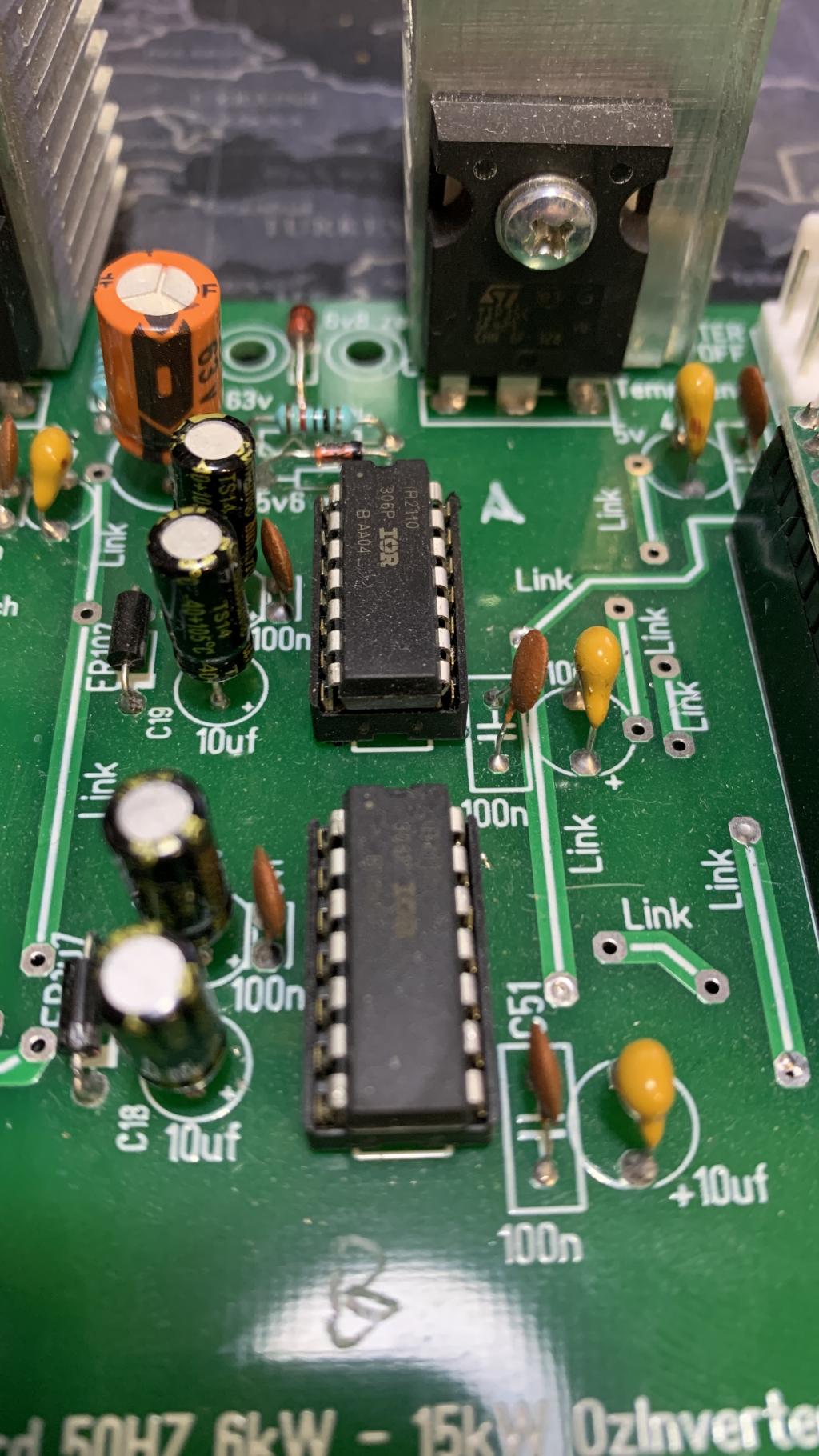
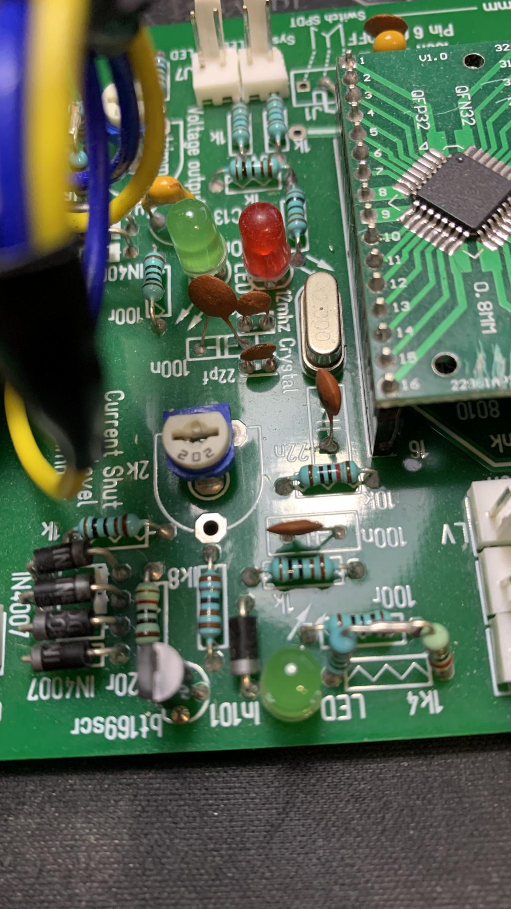
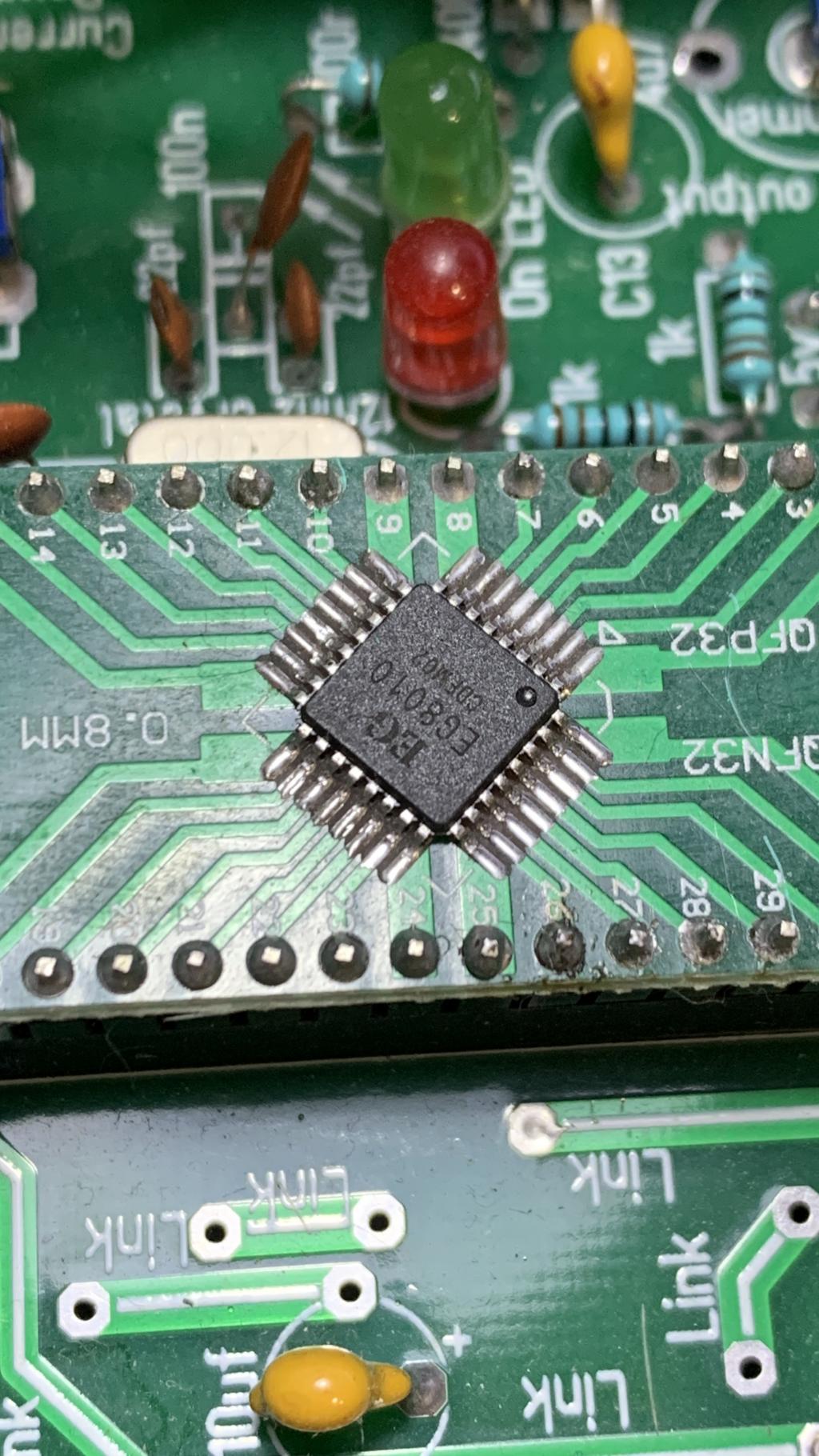
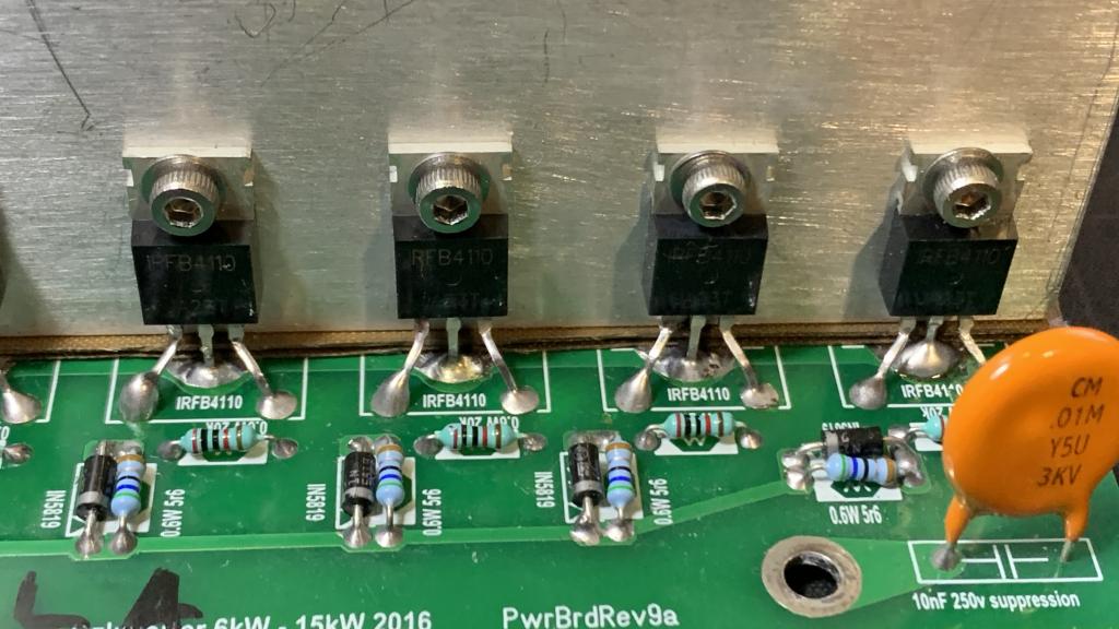
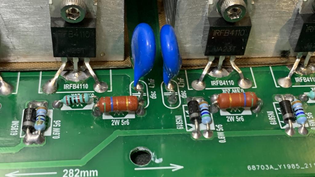
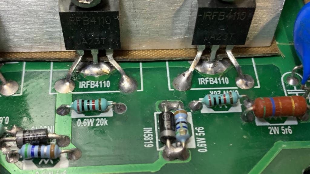
the power board pics
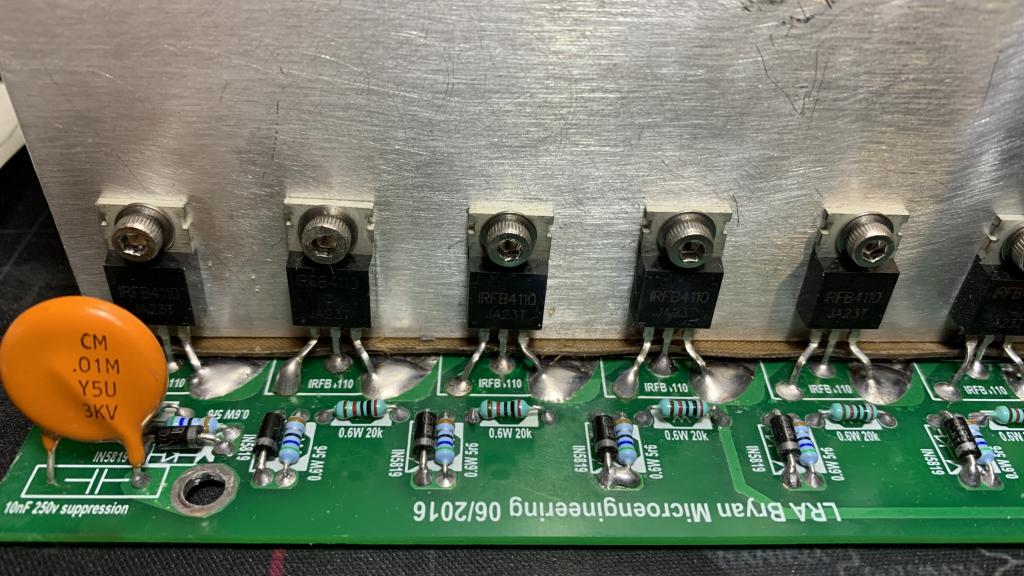
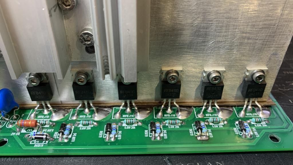

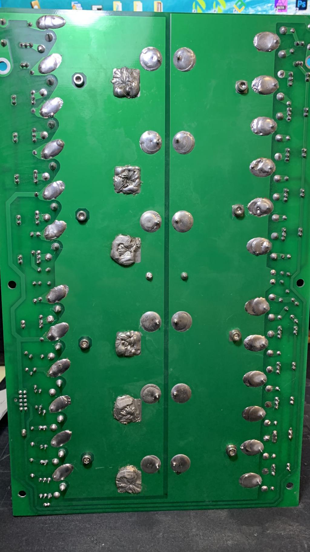
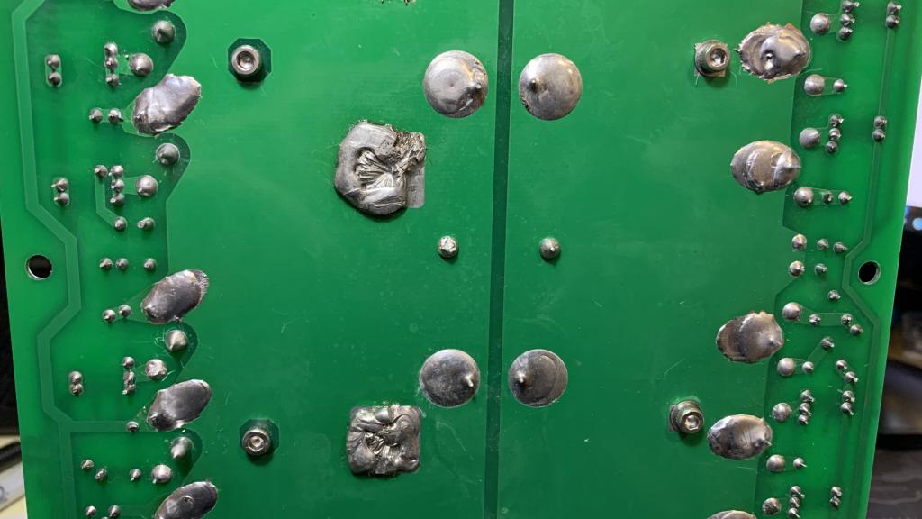
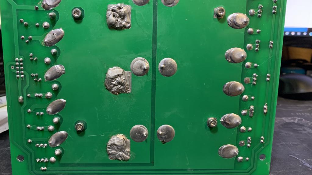 |
| |
mab1
Senior Member
Joined: 10/02/2015
Location: United KingdomPosts: 165 |
| Posted: 12:44pm 25 Apr 2024 |
Copy link to clipboard |
Print this post |
|
Re transformer:
Well if you had it connected to 230v mains and it was lighting a bulb it would have shown up a shorted turn by the shorted turn getting very hot fairly quickly, so it's probably ok.
I'm not sure the inductor would cause a blow up anyway so lets not worry about that yet.
Regarding the gate testing: i would be using a diode test between the gate abd the corresponding gate driver pins and verify that i see the 5.6ohms and diode basically. Your soldering looks good to me, but it's essentially double checking for solder bridges where there shouldn't be, or bad joints by testing.
Certainly a good idea removing the caps and powering up with just the bare minimum 4 fets for testing. |
| |
jakesea
Newbie
Joined: 30/09/2023
Location: United KingdomPosts: 8 |
| Posted: 06:54pm 25 Apr 2024 |
Copy link to clipboard |
Print this post |
|
ok, thanks mab1
I am planning to start de-soldering the components tomorrow.
I will test the gates before switching it on next time  |
| |
nickskethisniks
Guru
Joined: 17/10/2017
Location: BelgiumPosts: 416 |
| Posted: 08:29pm 25 Apr 2024 |
Copy link to clipboard |
Print this post |
|
Nice work, looks very neat, I'm sorry it blew up.
A 1K resistor might do the trick, it's just to bleed some energy off the parasitic capacitances in the circuit.
I would also inspect the ribbon cable again to make sure it is the right way.
Yes the voltage feedback would probably trigger the under voltage at the output, it will start to ramp up the pwm a few times and will then go in error, I think it wants to see 3V at the feedback pin of the egs chip. So 12V dc instead of the transformers output would work, make sure you don't put that 12V straight to the chip, you will destroy it that way.
I reread my topic I started a few years ago about my build (not a lot of info, for you though there are better documented threads to read)
https://www.thebackshed.com/forum/ViewTopic.php?TID=10304&P=2
One thing I read was that I had trouble with using a 13V zener and that it should be 18V to make the voltage to feed the gatedrivers. I've ended up using a seperate 15V supply for the gate drivers, also, I've used the ir2010drivers instead of the suggested ir2110 drivers.
Edited 2024-04-26 06:43 by nickskethisniks |
| |
jakesea
Newbie
Joined: 30/09/2023
Location: United KingdomPosts: 8 |
| Posted: 11:04am 26 Apr 2024 |
Copy link to clipboard |
Print this post |
|
nickskethisniks,
Thanks a lot - I tried my best
I checked the ribbon for continuity but not if it's the right way - will do.
I am about to order some more components so I will get ir2010 then.
In the manual, 18v zener is crossed out and changed specifically to 15v so that is what I have now and I will try again with 15v but I will keep it in mind and change it to 18v if necessary.
I am going to de-solder and follow the guidance you all have given me and report back
I am very grateful for all the input and advice |
| |
jakesea
Newbie
Joined: 30/09/2023
Location: United KingdomPosts: 8 |
| Posted: 02:36pm 03 May 2024 |
Copy link to clipboard |
Print this post |
|
Finally I was able to come back to the inverter after a few days wait for new components to arrive and two days of unsoldering, cleaning, checking...
So, I have replaced both TIP35, three zener diodes just to be sure (15v, 6.8v, 5.6v) and both ir2110 drivers (these two were faulty for sure and I also have ir2010 in reserve). I left current eg8010 for now but I have new ones ready to go in if necessary.
I have checked:
feedback transformer
ribbon cable for continuity and correct position
connected to power supply 48v ressticted to 1A just for an initial power board check
voltage on one tip35 and on VCC of ir2110 is 14.56v
voltage on the second tip35 and reference voltage on pin 17 of eg8010 is 4.88v
frequency on pins 10 and 11 is 12MHz
then I moved on to check the values on the output of the ir2110
below is a picture of the output of the 2HO (pin 4 of the ribbon, pin 7 of the bottom ir2110)
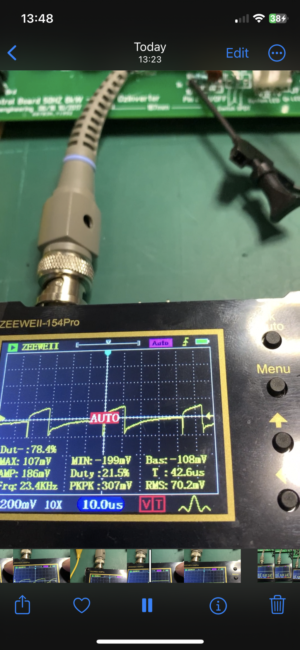
these are pictures of 2LO (ribbon pin 8, bottom ir2110 pin 1)
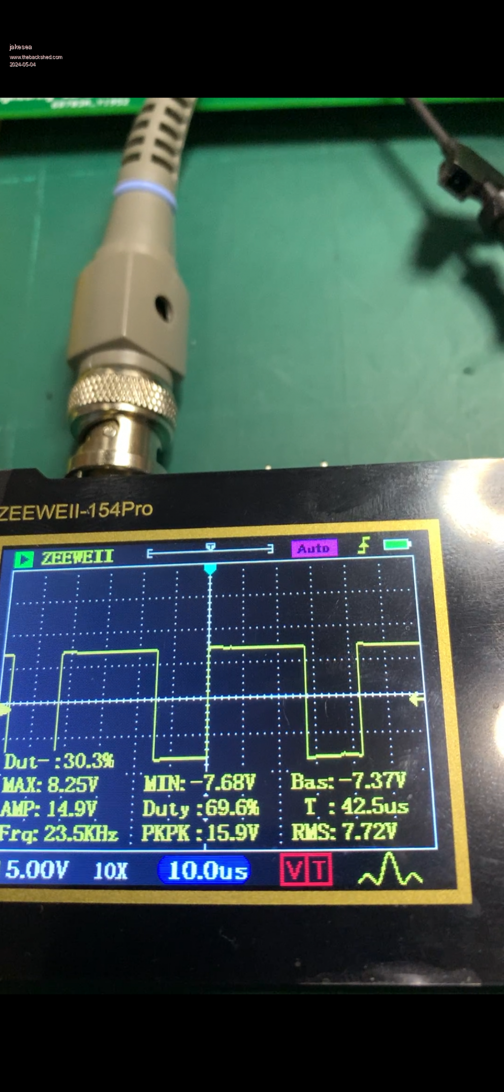
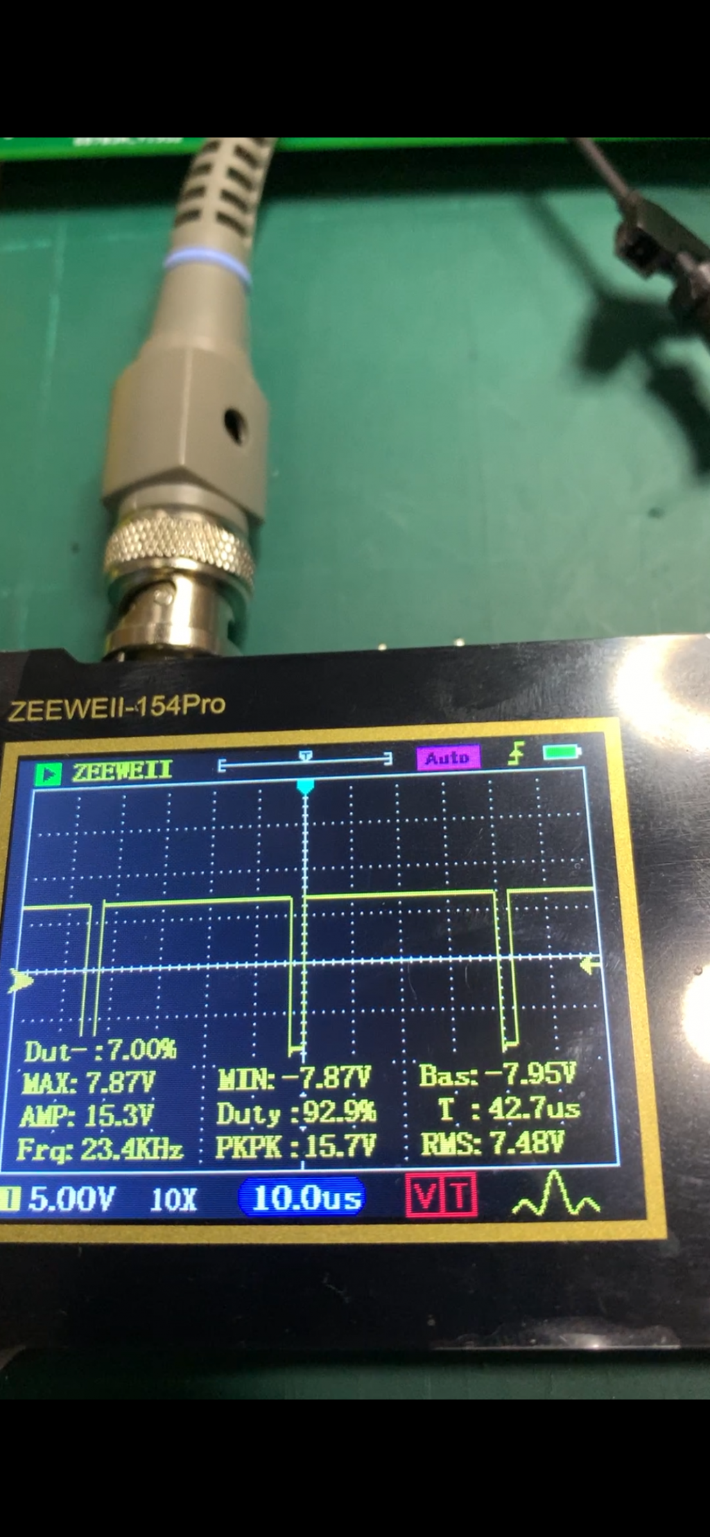
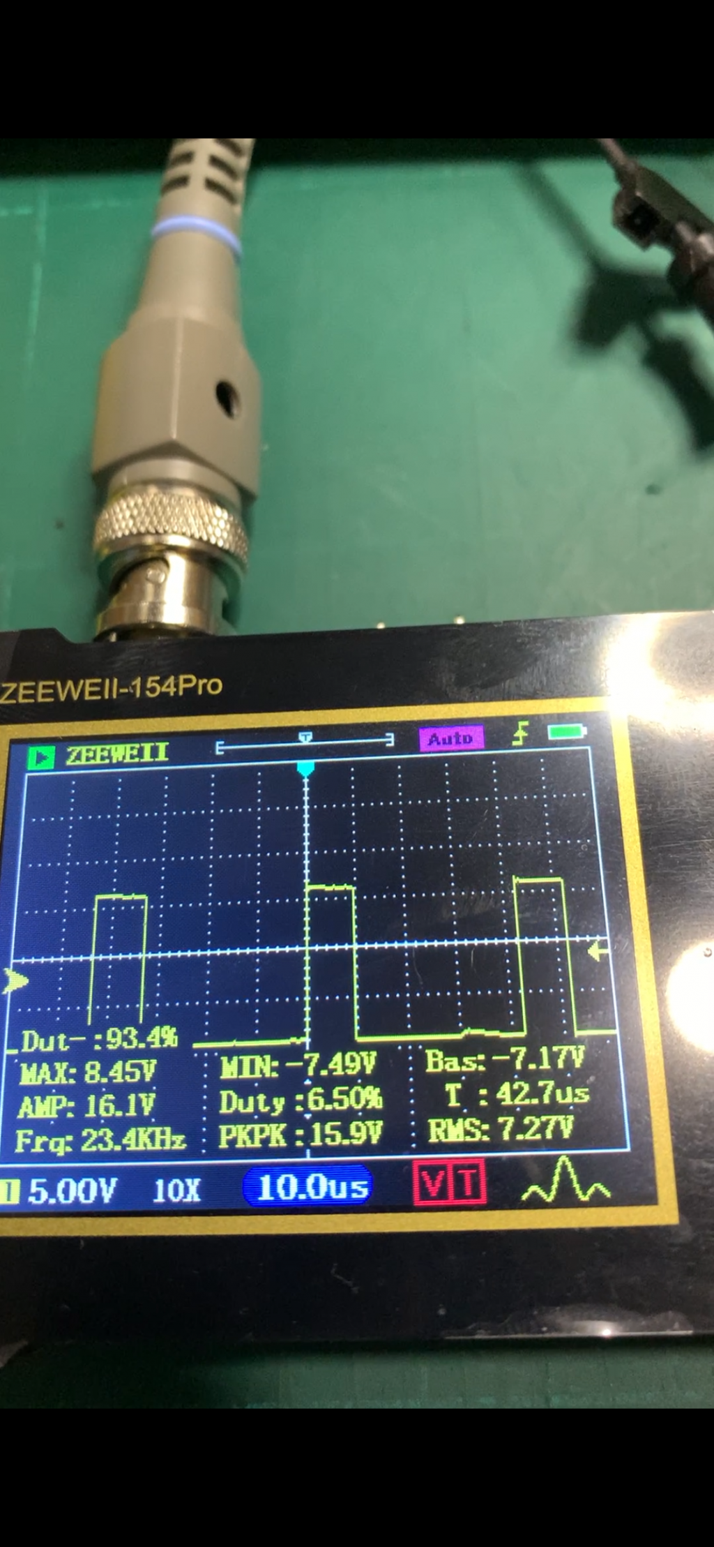
then 1LO (ribbon pin 3, top ir2110 pin 1)
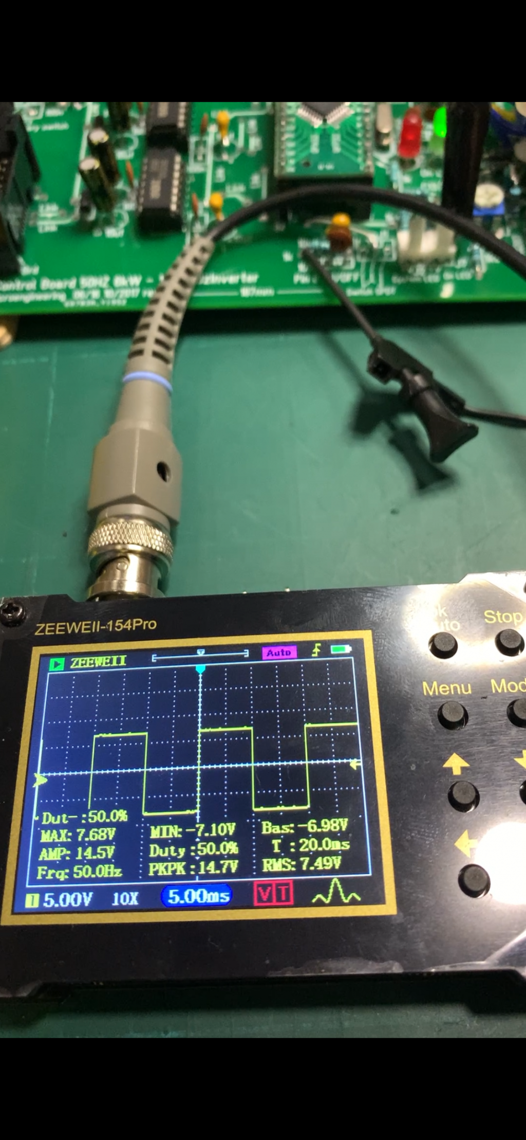
and finally 1HO (ribbon pin 7, top ir2110 pin 7)
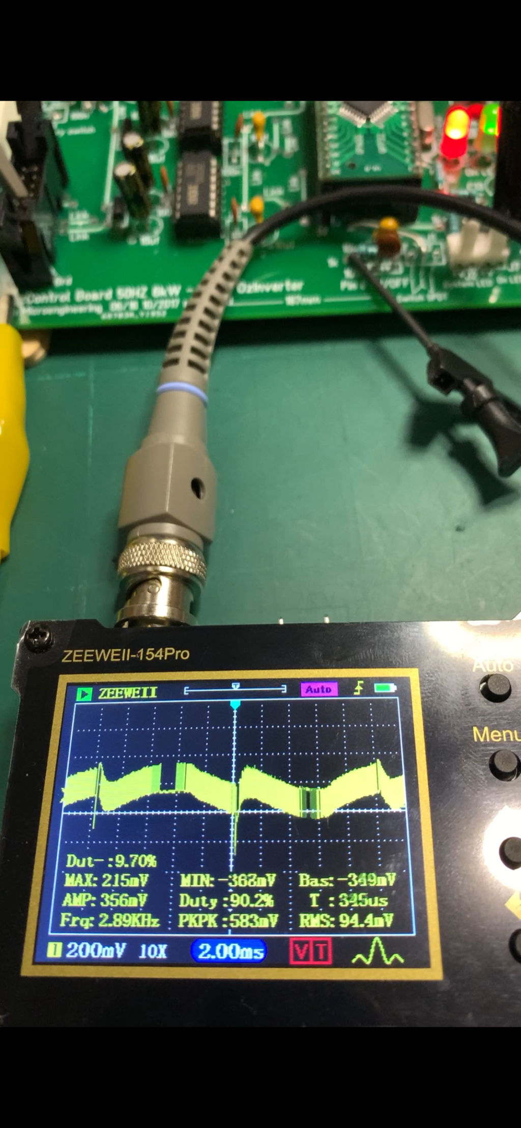
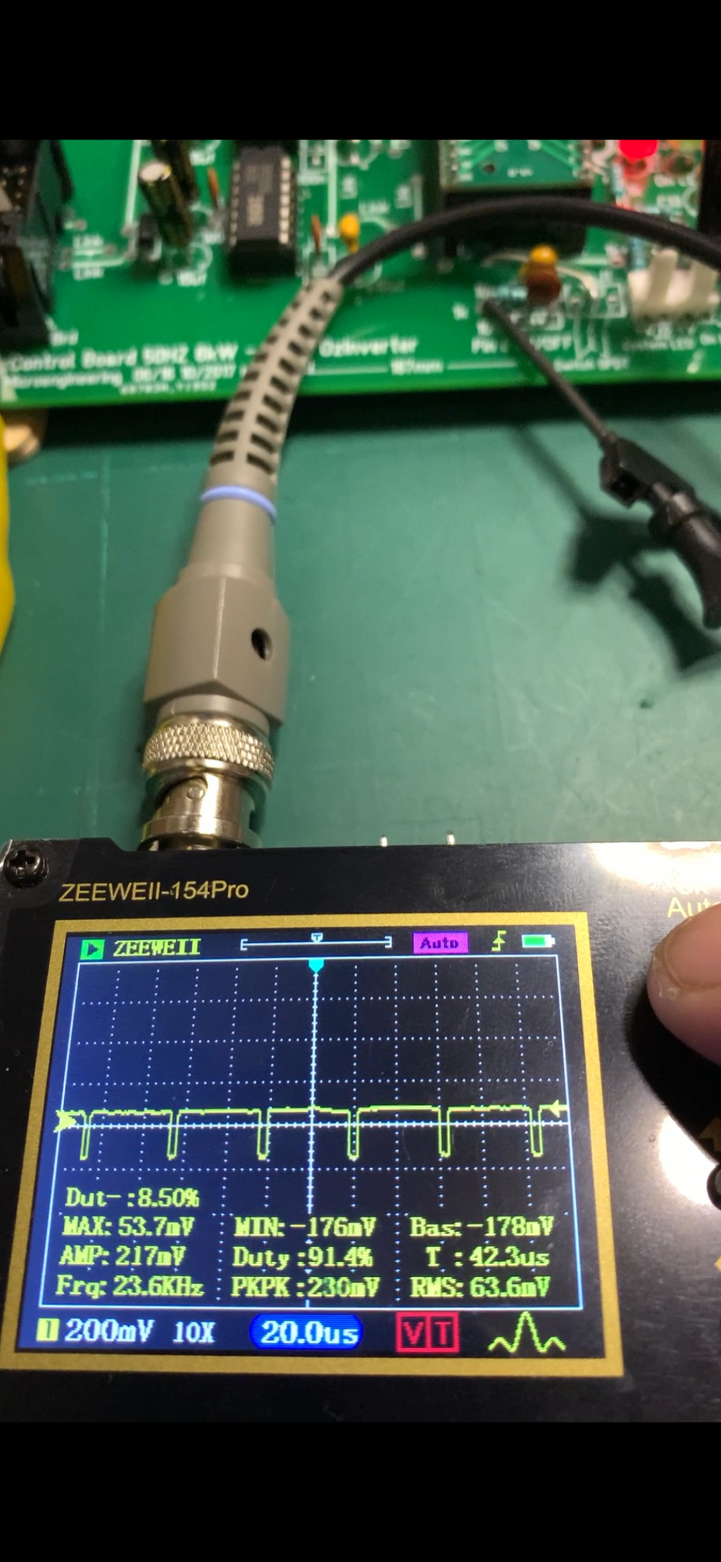
There isn't much time to take the photos as the board goes to under-voltage error after couple of seconds.
Could someone be so kind to comment on these values, please? Are they what I should be seeing at this stage?
Thanks |
| |
