Notice. New forum software under development. It's going to miss a few functions and look a bit ugly for a while, but I'm working on it full time now as the old forum was too unstable. Couple days, all good. If you notice any issues, please contact me.
PhenixRising Guru Joined: 07/11/2023 Location: United KingdomPosts: 2098
Posted: 07:27am 16 Jun 2026
Copy link to clipboard
Print this post
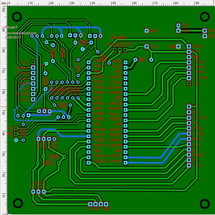
Quick observation: Did you run the DRC?
The square pad looks a bit close to the track.
Also, if the pad remains green, it's not thru-hole (TH) which might be what you intended, dunno.
mozzie Guru Joined: 15/06/2020 Location: AustraliaPosts: 468
Posted: 08:17am 16 Jun 2026
Copy link to clipboard
Print this post
G'day Bryan, If you are making changes to the PCB's, a couple of suggestions:
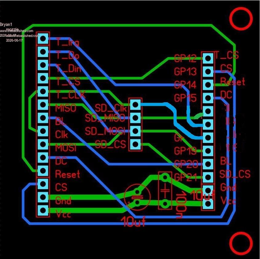
If possible, change GP16/GP17/GP18 on the LCD PCB to match the main PCB, keeping the order of both the same makes fault finding easier. Could also use IDC cable or plug direct while testing.
Add 10uf / 100n bypass caps to the LCD board 5V to GND
Put options for both pull up and pull down resistors on GP1 (enable) for different applications.
Just a few thoughts.
Hard to believe they can produce the boards for that cheap, almost makes making them at home expensive. Can't beat 2 hour turnaround though
Regards, Lyle.
Bryan1 Guru Joined: 22/02/2006 Location: AustraliaPosts: 2297
Posted: 08:42am 16 Jun 2026
Copy link to clipboard
Print this post
yea I nearly caught myself out today with the missmatch as the CLK is labeled differently so in the morning I will take all this onboard when I revisit Sprint Layout.
Anyway mate if you have any updated code could you pass it along as I did spend hours today trying to workout Claudes code and why it won't show the machine position. Now i did try claude today but after 3 questions it cut off.
matherp Guru Joined: 11/12/2012 Location: United KingdomPosts: 12034
Posted: 08:50am 16 Jun 2026
Copy link to clipboard
Print this post
Even for a PCB this simple my strong recommendation is to use a proper PCB package that starts with a schematic. EasyEDA is free, easy to use, and fully integrates with JLCPCB. Get the schematic right and the physical board will be right. Saves so much time and money in the long run. Also, it is much easier for others to help check the designs. Just post the schematic and then any feedback is easy to incorporate before wasting copper. Just my two-penny worth
PhenixRising Guru Joined: 07/11/2023 Location: United KingdomPosts: 2098
Posted: 10:25am 16 Jun 2026
Copy link to clipboard
Print this post
And rumour has it (Gemini) that they will soon have an AI assistant.
mozzie Guru Joined: 15/06/2020 Location: AustraliaPosts: 468
Posted: 04:25pm 16 Jun 2026
Copy link to clipboard
Print this post
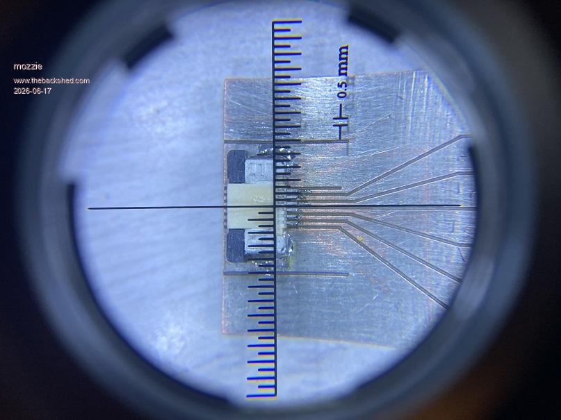
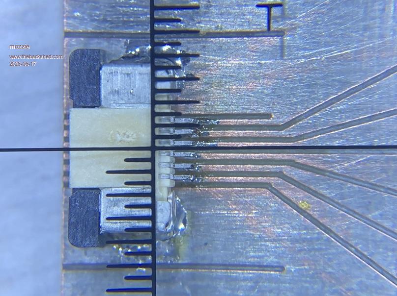
G'day, As most of the PCB's used here are more of the "Power" than "Motherboard" variety they have been designed on an ancient CAD package (WIN 98) and cut with a CNC engraving machine, results have been surprisingly good:
This is 0.5mm pitch connector for GT911 touch screen. Considering a PCB can go from idea to finished product in 2-3 hours its hard to beat. just don't look too close at the soldering
However with the prices from JLCPCB and others and the services they offer, it might finally be time to bite the bullet and give EasyEDA or one of the similar packages a try.
Bryan, I've had the flu (covid?) for the last week so any programming was utter rubbish, the grey cells turned to snot.... Will have a crack over the next couple of days.
Regards, Lyle.
Bryan1 Guru Joined: 22/02/2006 Location: AustraliaPosts: 2297
Posted: 12:59am 17 Jun 2026
Copy link to clipboard
Print this post
Morning Guy's Lyle I took on all your suggestions mate and found it was easier to change the stepper board LCD pin assignments to suit the LCD Board. Now above the pico 2 is a 3 pin header so GP01(Enable) can be pulled up to 5V or Gnd and I moved the I2C breakout so it is clear of the RTC, did a DRC and made sure all my changed did confirm and like usual the S1 silkscreen pads seem to cause errors where simply deleting the offending one's with a new componet does fix the problem.
Peter I do get what your saying where when one designs a new project a schematic should be done first so I did have a look at EDA this morning and it went straight over my head as I would need to be ontop of all the new components etc.
Now with this stepper board for example Lyle did give a schematic of the step/direction outputs and yes the Enable(GP01) should of had the pullup/pulldown option put in. Then a LCD output and why I didn't make the LCD outputs the same one can put it down to grey cells
Well for my first attempt one could expect something to go wrong but the board did work nicely and just a few hacks were needed. Like with the LCD board getting the MISO/MOSI pin wrong was an easy fix to get it working.
Now at $3.50 for 5 boards it's not going to break the bank for a V2 revision and now you have done the GUI addition for LCD screens I'm sure this 4" LCD will become obsolete
Regards Bryan
mozzie Guru Joined: 15/06/2020 Location: AustraliaPosts: 468
Posted: 02:44am 17 Jun 2026
Copy link to clipboard
Print this post
Hi Bryan, I guess its up to you mate but I would prefer to keep the I/O in order and change the LCD PCB to suit, could be my OCD kicking in
Pretty sure this will work, not sure how easy it is to edit in your program.
I have asked Peter about a change to the stepper system to make the calibration routines easier, now I'm nearly over the flu hopefully some progress can be made
Regards, Lyle.
Bryan1 Guru Joined: 22/02/2006 Location: AustraliaPosts: 2297
Posted: 02:58am 17 Jun 2026
Copy link to clipboard
Print this post
Lyle the edits I did to the stepper board now confirm with the LCD board and the pin assignments didn't change also now I do have the LCDBoard working with the touch SPI hack I did best not to change it I think.
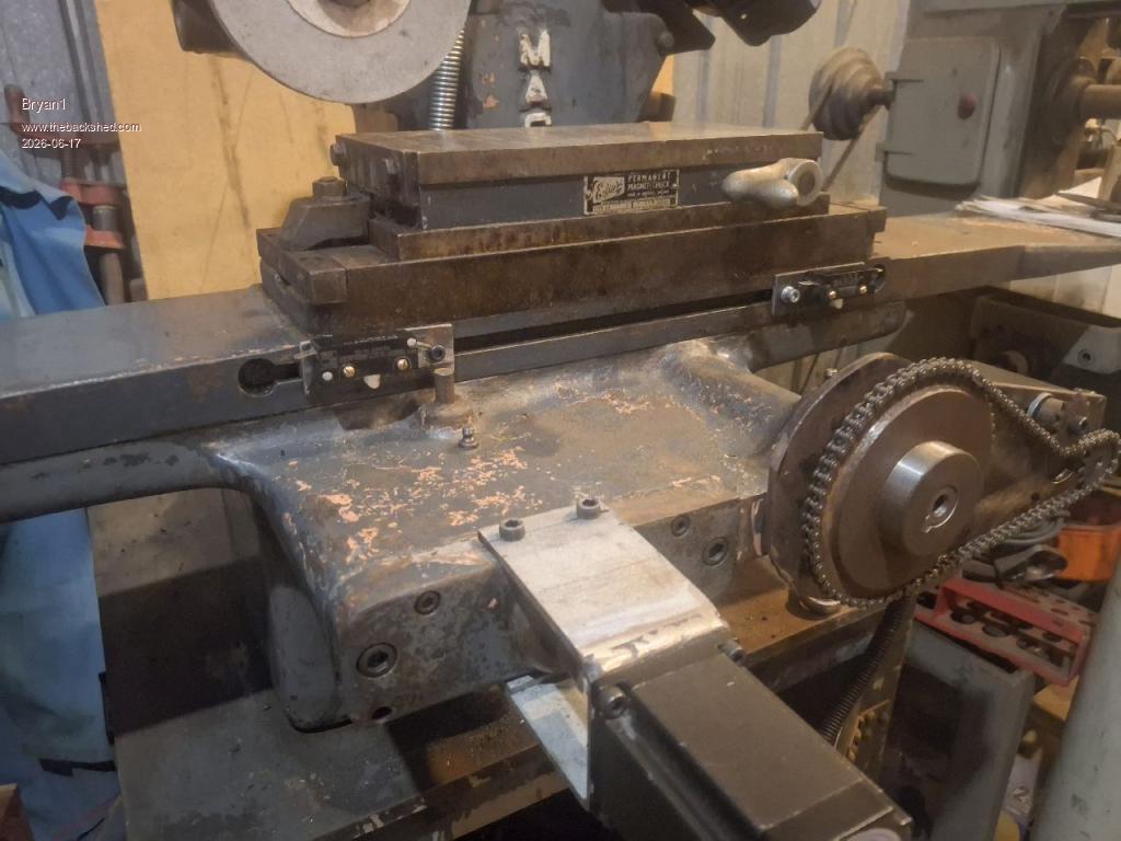
Now I did find some old limit switch's to use for the X Axis So cut some 3mm plate to 75x25mm and using some 8x7 key steel the 8mm is right for the slot so adjustment can be kept inline.
Found some M3 x 12 socket head cap screws for holding the key steel so dialed in the vice on my bridgeport mill so it's nice and square. Now for securing the limit switch I need some M3 x 20 bolts and the search is still on but lunch is in the way so time for a break.
Now if your happy with my mod's I can get these boards off today and the testing can still be done where the RTC can wait for the new revision.
Regards Bryan
mozzie Guru Joined: 15/06/2020 Location: AustraliaPosts: 468
Posted: 03:17am 17 Jun 2026
Copy link to clipboard
Print this post
Hi Bryan, I was more thinking of trying to keep the I/O in order on both boards to make fault finding easier, GP12-GP21 as on the original Main PCB and change the LCD PCB to suit as its already been modified.
It'll work either way so no real problem
You could also make an adapter board for VGA/DVI output using the same pins, this was the reason for specifying them
Regards, Lyle.
Bryan1 Guru Joined: 22/02/2006 Location: AustraliaPosts: 2297
Posted: 03:28am 17 Jun 2026
Copy link to clipboard
Print this post
Well mate with the VGA/DVI I will leave that you to make the schematic so I can get an understanding as this is all new to me. I do have several old 14" VGA screens here that I kept as I knew oneday they would find a use
Anyway thats lunch over so time go back and find some 20mm long M3 screws and if all else fails the limit switch holes are getting drilled out to 5mm as I do have those bolts
Regards Bryan
Edit: Well that didn't take long with fresh grey cells opened the second draw in my Dad's old case and sure enough found some 1/8" BSW cheesehead screws 1" long A quick check in my toolbox soon found some 1/8"BSW taps so now I can get on and get the limit switch mounts made. Edited 2026-06-17 14:02 by Bryan1
Bryan1 Guru Joined: 22/02/2006 Location: AustraliaPosts: 2297
Posted: 06:45am 17 Jun 2026
Copy link to clipboard
Print this post
Well finally got the limits mounted also last week gave the surface grinder a bath to clean it up.
So in the morning I will make a strike plate that sits on that centre post so the limits can gently close and they fully adjustable too
I am pretty happy I got this far today and setting them up in the morning will be a fun task.
Regards Bryan
matherp Guru Joined: 11/12/2012 Location: United KingdomPosts: 12034
Posted: 07:24am 17 Jun 2026
Copy link to clipboard
Print this post
I need to do a build but check STEPPER TUNE in the updated manual
mozzie Guru Joined: 15/06/2020 Location: AustraliaPosts: 468
Posted: 12:52pm 17 Jun 2026
Copy link to clipboard
Print this post
G'day, Peter, just downloaded latest version, will test and report back. A quick read of the manual and that is pretty much spot on. Thanks again
Bryan, Looking good
Regards, Lyle.
Bryan1 Guru Joined: 22/02/2006 Location: AustraliaPosts: 2297
Posted: 06:16am 25 Jun 2026
Copy link to clipboard
Print this post
Well had a go at coding today and got no where as everything I tried resulted in an error
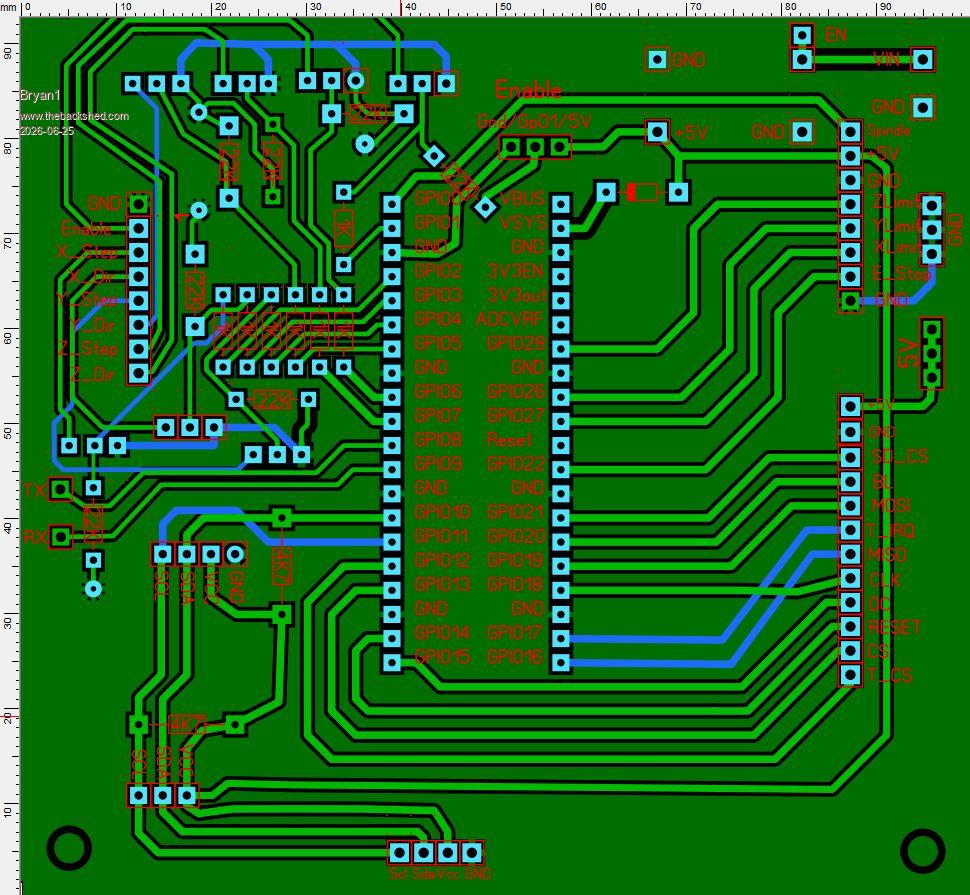
Anyway as we need 3 pullups for the DM556's added a 3 pin header also put in a 3 pin header for the limit ground connections. Also changed all the pads over to square as I have found they are easier to solder
Anyway it is time to get these boards off to JLCPCB so with the changes it may just actually work
Regards Bryan
mozzie Guru Joined: 15/06/2020 Location: AustraliaPosts: 468
Posted: 02:14pm 25 Jun 2026
Copy link to clipboard
Print this post
G'day Bryan, Looks like Claude still has a bit to learn about writing MMBasic code, got it pretty close but makes the same mistakes I do
A few things adjusted and this works with V6.03.00RC21 but should also work with most previous versions.
There are still a lot of things missing but it should do a basic cycle of the grinding machine.
If you haven't already sent off those PCB files, can I ask you to consider changing the main PCB back to the original layout with GP12-GP21 in order and change the LCD PCB to suit, I do similar kinds of things as a "Shortcut" now and then and it comes back to bite me on the ass every time, particularly during fault finding.
Once again, its your project so up to you. Otherwise its looking good
A VGA adaptor board could be made and it'll be a lot easier with those pins in the correct order.
Regards, Lyle. Edited 2026-06-26 00:17 by mozzie
PhenixRising Guru Joined: 07/11/2023 Location: United KingdomPosts: 2098
Posted: 01:53pm 04 Jul 2026
Copy link to clipboard
Print this post
Do we have a "Motion Hold" (pause)?
During a move, a hold signal would bring motion to a controlled stop, based on the programmed decel.
I don't see a mechanism for this (?)
mozzie Guru Joined: 15/06/2020 Location: AustraliaPosts: 468
Posted: 02:02pm 04 Jul 2026
Copy link to clipboard
Print this post
G'day Phenix, Not AFAIK at the moment, although it would be a great feature to be able to pause the system and still know the position for restart.
Regards, Lyle.
PhenixRising Guru Joined: 07/11/2023 Location: United KingdomPosts: 2098
Posted: 04:24pm 04 Jul 2026
Copy link to clipboard
Print this post
We'll mostly be spoon-feeding buffers and so we could just look for a HOLD condition and quit feeding data. Long moves could be broken up into shorter segments and again, before adding to the buffer, check for HOLD condition.
Bryan1 Guru Joined: 22/02/2006 Location: AustraliaPosts: 2297
Posted: 04:26am 08 Jul 2026
Copy link to clipboard
Print this post
Well those stepper boards turned up this morning so now on soldering up the boards and I have decided to move the DM556's to the inside of the cabinet, also on mounting the LCD into that project case and found a red push button switch to use as the E-Stop
So got a bit of work to do to get it all setup then the fun can start.
Just on thinking about all the connections from the PCB as with my Element 14 order in order to get free shipping I bought a end ferrule kit with a good setting tool Just tested it out with the Cat5 single core wire and it crimped nicely so now I can make my own connections which can be removed easily.
Got on and did a google search and got 2,3,4,8,12 ones coming from Ali so the wait goes on.
Got the limit switch's so got them to do and I'm thinking of making them the same as my CNC.
Regards Bryan Edited 2026-07-08 15:25 by Bryan1
Page 21 of 22
Print this page
The Back Shed's forum code is written, and hosted, in Australia.

 Notice. New forum software under development. It's going to miss a few functions and look a bit ugly for a while, but I'm working on it full time now as the old forum was too unstable. Couple days, all good. If you notice any issues, please contact me.


 Print this post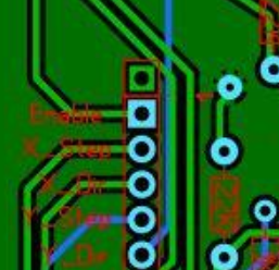



 Will have a crack over the next couple of days.