
|
|
Forum Index : Microcontroller and PC projects : Stepper Project
| Author | Message | ||||
| mozzie Guru Joined: 15/06/2020 Location: AustraliaPosts: 403 |
G'day Bryan, Great to see you are making progress  I think the command you are looking for is PEEK(STEPPER BUFFER) ' prog to test stepper functions Option default integer On Error skip Stepper close SetTick 200,Show_Pos Stepper init 0.05,32,,1 Stepper axis x,gp0,gp1,gp5,,200,400,50,5 Stepper axis y,gp6,gp7,,,400,600,100,5 Stepper position home Stepper run 0 Stepper gc g1 x100 y80 f500 Stepper gc g4 p1000 Stepper gc g0 x0 y0 Do Pause 100 Loop Until Peek(stepper active)=0 ' wait until motion complete Pause 250 ' wait for final position update Stepper close End Sub Show_Pos Print @(100,108),"X-POS = " Str$(Peek(stepper x),-4,4) Print @(100,120),"Y-POS = " Str$(Peek(stepper y),-4,4) Print @(100,132),"Buffer = " Str$(Peek(stepper buffer),4) End Sub Pretty sure this is the latest version of the Stepper Reference. Stepper_Reference.pdf Regards, Lyle. |
||||
Bryan1 Guru Joined: 22/02/2006 Location: AustraliaPosts: 2155 |
Hi Lyle yea mate getting the DM556 working today was a huge step in the right direction for me so now I do have to get my head around coding all this up. Now what I did find when I did those buttons to mimic the stepper limits it clearly states for the same axis the same pins can be used but when I did try that got an error so thats why 6 off in/out pins are used + one for the E-Stop. As I do have my HDMIUSB board up in the shed now it's right next to the surface grinder so when those DM556's arrive I will have a go with that board as with the mouse and keyboard to go setting up the parameters for the grinder will be a breeze. Now I do think we can get away from using ball screw on the Y and Z axis and make an allowance in the code for the backlash. But with the Z axis I do think a ball screw should be used as we do want precision when we set the grinding wheel for the cut where just a few step pulses may be needed to get the depth. Also a damper could be installed to beef up the Z axis. So basically the X axis is just going to going back and forth at a predetermined distance and when it changes direction the Y axis can move the required distance to keep the cutting going, also once the X axis has gone back and forth the Z axis can be incremented down to set the level to get a good cut. So getting this all my head is one thing now putting all this into code is certainly going to test the grey matter. Regards Bryan |
||||
| PhenixRising Guru Joined: 07/11/2023 Location: United KingdomPosts: 2003 |
Don't know much about grinding; is there any benefit to variable speed on the X axis? |
||||
| mozzie Guru Joined: 15/06/2020 Location: AustraliaPosts: 403 |
G'day, Phenix, variable speed on the x-axis is required, as the thickness of the job changes you have to take very light cuts and slow the feed rate, especially when making or thinning shims. Bryan, pretty sure you can use the same limit input for both ends of an axis, but you need to specify all 3 axis even if not using them, IE: STEPPER HWLIMITS GP20,GP21,GP22,GP20,GP21,GP22 Agree that the X and Y axis are not going to matter much regarding backlash, need to pass the ends of the job on the X and overlap the passes on the Y anyway, so should be all good. The Z-Axis on the machine here is a leadscrew driven by a wormgear, so can probably hook a motor almost directly to it. That's after I move a ton of other gear to gain access to it again  I posted on the other thread regarding the enable signal being the wrong polarity, however from memory most of the stepper driver boards it is really a DISABLE signal so the current setup will work with the following circuit: 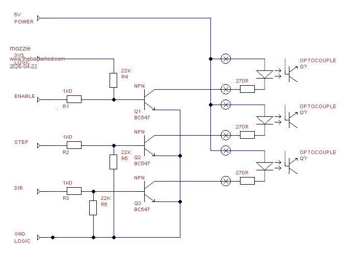 Transistor and resistor values are what I have most of, pretty much anything NPN and similar values should work. Regards, Lyle. |
||||
| Bryan1 Guru Joined: 22/02/2006 Location: AustraliaPosts: 2155 |
Now the subject has come up about the X axis needing to be variable speed could the F component of the G-code become a $ where a analogue input from a 5K pot is placed at the grinder so the X axis can be tuned for the startup of the job. Once the job is setup the AIN value can be kept for the duration of the job. Lyle I have plenty of those BC337 transistors so as I have them onhand I will use them and for the opto's I will have to source them. Now as I will be using my HDMIUSB board and my huge LCD I will have to start on the code so this project can move forward Now my idea is to have say input box's where each axis value can be set.Just a thought while pondering over the morning caffine. Regards Bryan |
||||
| phil99 Guru Joined: 11/02/2018 Location: AustraliaPosts: 3321 |
The optos in Lyle's circuit are the ones in the DM556 driver, you don't need to add them. See the circuit in the first post of the previous page. Edited 2026-04-22 09:13 by phil99 |
||||
| Bryan1 Guru Joined: 22/02/2006 Location: AustraliaPosts: 2155 |
Thanks for that Phil as I was still on my first caffine the grey cells were just unwinding  Anyway I found the cure for connecting MCCC to the HDMIUSB board as I went into Device Manager only to be told I was a normal user and couldn't change settings  So into User settings where I changed my account for the second time back to Administrator did a reboot and got back into Device Manager and the CH340 settings where the baud rate was 9600 so changed it to 115200 did another reboot and when I started MCCC it connected straight away So into User settings where I changed my account for the second time back to Administrator did a reboot and got back into Device Manager and the CH340 settings where the baud rate was 9600 so changed it to 115200 did another reboot and when I started MCCC it connected straight away On reading the manual that was the setting I needed to do so went and setup the RTC with time and date and now a few hours later the HDMIUSB board is keeping time Anyway I'm getting brought out of retirement to help out the Labourhire company now where every tradies nightmare seems to lose that 10mm spanner for me it was the 24mm socket  so off to Repco for a new one. so off to Repco for a new one. Now looking on the HDMIUSB board we have 12 in/out pins to use, so if we did use enable for every axis there wouldn't be enough pins for the limits so may aswell leave the enable off as on the DM558 the Enable pin is not used by Default. So lets do some pin assignments GP0, GP1 X DIR and Step GP2, GP3 Y DIR and Step GP4, GP5 X DIR and Step GP6 X limit GP7 Y Limit GP23 Z Limit GP26 E_Stop Which leaves us 2 spare pins to use, So Mozzie what do you think of these pin assignments and lets come to an agreement so the code made doesn't have any changes. Regards Bryan |
||||
| Bryan1 Guru Joined: 22/02/2006 Location: AustraliaPosts: 2155 |
Well Guy's when I worked at Monroe's I did get a set of shock absorbers and the rear ones were the wrong ones for my Forrester so just now thought lets get one out and see if it's around 550mm so it can be used as a damper for the surface grinder X axis and found it's going to fit like a T 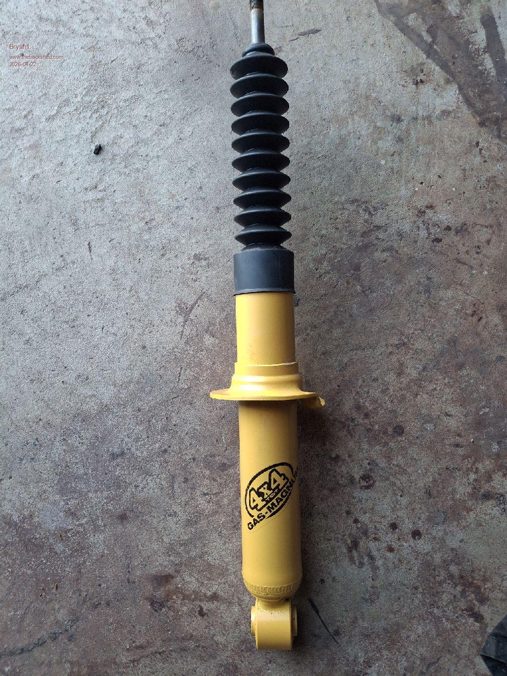 Just need now to make the brackets for it so it will be this weekends job then no need to install a ball screw as I can mount a stepper straight on the end of the leadscrew like I'll be doing with the X and Y axis. Now I had the idea of using a picture of the surface grinder as the background picture in the program file then put the box's close to the steppers for the data etc which would look pretty cool I reckon. So been learning how to xmodem in teraterm after I had to edit the baud rate to get tera term to work  Now after transferring the jpg file it comes out in 16 colours not high res when I look at the jpg. The FM means just one click to view it too so what setting would I need to put in so I can get a high resolution jpg that was transferred.This is the picture I used 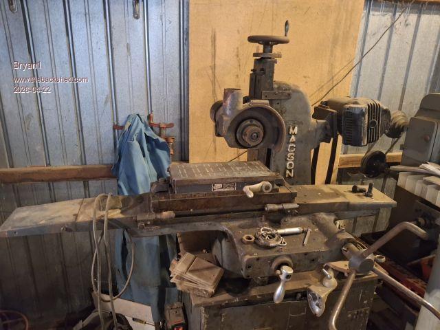 SG1.zip Edited 2026-04-22 16:03 by Bryan1 |
||||
| Bryan1 Guru Joined: 22/02/2006 Location: AustraliaPosts: 2155 |
On RTFM I tried out 800x600 Mode 3 and xmodemed a 65K res pic now the picture was a tad better but still like 16 colours so more reading to do I think |
||||
| mozzie Guru Joined: 15/06/2020 Location: AustraliaPosts: 403 |
G'day Bryan, Apologies for the slow response, been madly filling an order that snuck up on me, nearly done. It's going to take a few more days to clean down the machines and pick up all the swarf. Bloody aluminium being non magnetic makes it a bugger to clean up... Sadly at this point the surface grinder is a long way down the priority list, I can't even get near it at the moment. However I have found a spare Pico2 so will load that with the latest firmware and your options / IO pins and will test some ideas as time allows, and happy to help you with yours if I can. As you have probably realized, with the limitations of the PicoMite HDMI you can either have colour depth or resolution, but not really both. Its bloody good for what it is within those limitations. The surface grinder here will get an ILI9488 LCD so a much simpler screen will do: 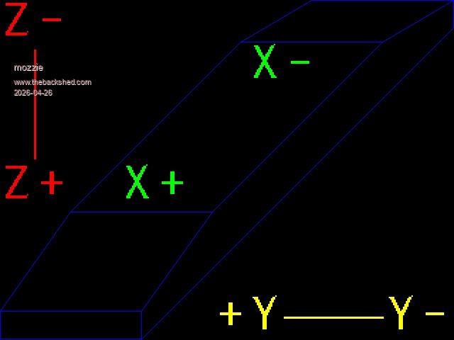 This was drawn with the code below (currently tested 640x480 HDMI mode 3) 'Prog to draw Surface Grinder MODE 3 Option default integer Box 0,439,200,40,1,&hff ' lower end Line 199,479,639,39,1,&hff ' lower diagonal Line 639,39,639,0,1,&hff ' upper vertical Line 639,0,439,0,1,&hff ' upper end Line 639,0,539,59,1,&hff Line 439,0,339,59,1,&hff Line 539,59,339,59,1,&hff Line 339,59,99,299,1,&hff Line 539,59,299,299,1,&hff Line 99,299,299,299,1,&hff Line 99,299,0,439,1,&hff Line 299,299,199,439,1,&hff Text 0,0,"Z-",,5,2,&hff0000 Text 0,230,"Z+",,5,2,&hff0000 Line 48,70,48,224,3,&hff0000 Text 300,415,"+Y Y-",,5,2,&hffff00 Line 400,447,540,447,3,&hffff00 Text 170,230,"X+",,5,2,&hff00 Text 350,60,"X-",,5,2,&hff00 End Still need to scale for LCD and add feed rates and positions for CNC side. More work to do... Regards, Lyle. |
||||
| Bryan1 Guru Joined: 22/02/2006 Location: AustraliaPosts: 2155 |
Hi Lyle the more I'm thinking about this I do think that big 2350B board I have here that I was using to test the X axis on my CNC may be a better suit as it has plenty of in/outs and what I find with that 3.5" ILI9488 LCD it is hard to read with these old eyes of mine. Now lets say a 7" or 9" 8 bit LCD touch screen may be the better LCD as a larger font could be used to make viewing that much easier. Now being able to assign the the D0 pin as GP0 isn't on the board using a LCD that is described in the manual I do think will be the best one to use. Just need to find one will be the fun part as with Ali I found it is hit and miss. So if we setup the LCD in GUI mode setting the axis controls can be made so once all the settings are done the start button can be touched. I checked the tracking on those DM556's and it is saying the 29th so in this next week I do need to purchase 3 off flexible couplings and purchase one more stepper motor as I have 2 of those 2.4Nm ones here another one of the same will be the go.Regards Bryan |
||||
| Bryan1 Guru Joined: 22/02/2006 Location: AustraliaPosts: 2155 |
Well I guess using a SSD1963 is out as I tried out testing that one had to see if it was still working. Well talk about frustration I installed V6.03B1 and when I did the option LCDPANEL for the SSD1963 when MCCC disconnected it said COM9 is disconnected and didn't reconnect infact the COM port was lost and looking in Device Manager only COM3 was there and in Universal Serial Bus was an error saying couldn't connect to unknown device. Pressing the reset button on the board did nothing and reflashing the new file just kept doing the same thing. That was this morning and I helped out my daughter move some gear with my trailer. Now this arvo decided just to put the board back with the old setup with the ILI9488 and it just worked so gladly I didn't brick the board When my daughters boyfriend came up to get rid of Bob that admin on this computer that stopped me installing teraterm I put on the HDMIUSB board only to find mt old TV was just clicking and refusing to display anything. So 800x600 in mode3 is out and back to 640x480 is what I will stay with. Anyway I started the HDMIUSB board with the TV off and both Teraterm and MCCC was unusable so setup the programming cable and put V6.03B1 on did the option reset HDMIUSB and all good so no damage done. I put Comfortably Numb using the FM and now it's pouring down with rain a few MP3's may have to get played as can't hear the radio Edited 2026-04-26 16:24 by Bryan1 |
||||
| mozzie Guru Joined: 15/06/2020 Location: AustraliaPosts: 403 |
G'day Bryan, Sounds like the Gremlins have moved in  Just as a matter of interest, are you trying to use GP0 on the RP2350B board? This is the PSRAM enable pin and will cause the board to lock up if you use it for anything else, such as the display. As for the LCD panel, it won't really matter which display each of us use, the core program will be the same. Good programming would declare the IO pins as constants at the start of the program, might have to try and be a good programmer for once I have loaded V6.03.00B2 on both the HDMIUSB and RP2350B boards and they are both working, Peter has added STEPPER GS "STRING" so we can easily import from a file and make G-Code strings in a program. More testing to follow. Regards, Lyle. |
||||
| Bryan1 Guru Joined: 22/02/2006 Location: AustraliaPosts: 2155 |
Just had a knock on the door and those DM556's have arrived |
||||
| Bryan1 Guru Joined: 22/02/2006 Location: AustraliaPosts: 2155 |
Ok been pretty busy with my Daughters new car she bought and it's back at the car yard getting fixed. Anyway this morning went for drive upto Murray Bridge to Eastside Bearings and found they only had one flexible coupling 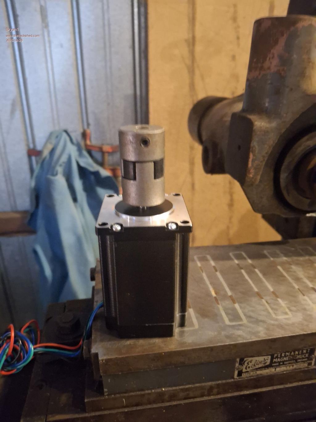 Now this coupling has an 8mm bore and fits the stepper shaft very nice so that takes care of 2 steppers and the other couplings should be a couple of days away. Also I go onto ebay and ordered another stepper motor so that should be here in about a week.Now for mounting the stepper motors I'm going to machine up a hard coupling so the alignment and spacing will be right so the flexible coupling can be installed esily and right. Power for the DM556 will be the same as my CNC which is my shed battery bank and I do have this 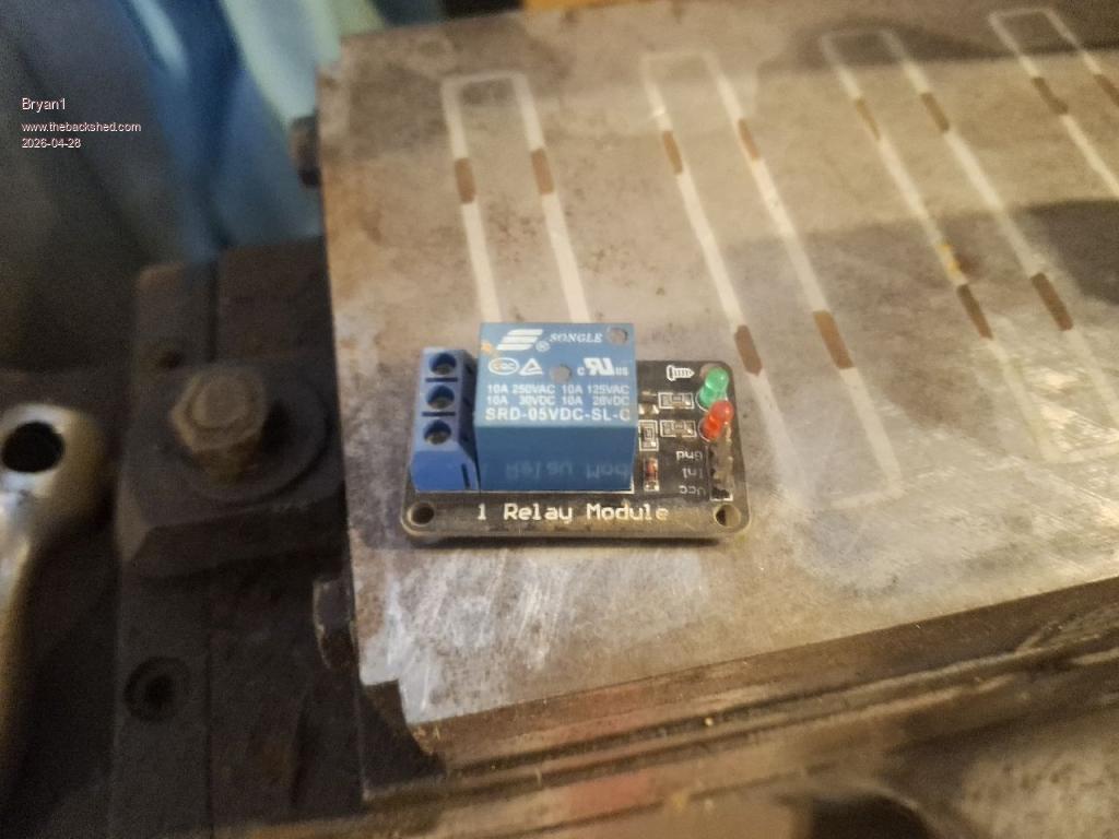 So the DM556 power supply can be turned on by a output pin and also maybe used with the E_Stop for safety when/if something goes wrong. So my plan is get all the stepper motors installed then the fun can start with the code. Regards Bryan |
||||
| Bryan1 Guru Joined: 22/02/2006 Location: AustraliaPosts: 2155 |
Ok as I didn't have any pico 2 boards I have ordered 2 of them on Ali so the next thing is finding a decent 7" screen with touch which can be the base for the project. For now we can use the ILI9488 for the GUI code and I can use my big 2350B board for now for testing etc. Then over time I can design up a PCB in Sprint Layout and as the min order is 5 Lyle will have a couple of boards for himself. My idea of using a pico 2 board we have GP0 to use so it can be hooked up using the pico manual method Anyway close to time to packup my metal detector as a local friends wife's gold necklace is in the yard somewhere where the kids left it so it will be fun trying to find it Who said being in semi retirement was boring |
||||
| Bryan1 Guru Joined: 22/02/2006 Location: AustraliaPosts: 2155 |
That third stepper motor just turned up today so went and collected it and the 2350A pico2 boards should be here withing the week so thought better get on mounting these stepper motors I machined up a hard coupling to use and reamed a 8mm bore for the stepper motor shaft so when the stepper motor is removed and reinstalled until it's a nice slide in fit more adjustments are done to ensure the flexible coupling is aligned. 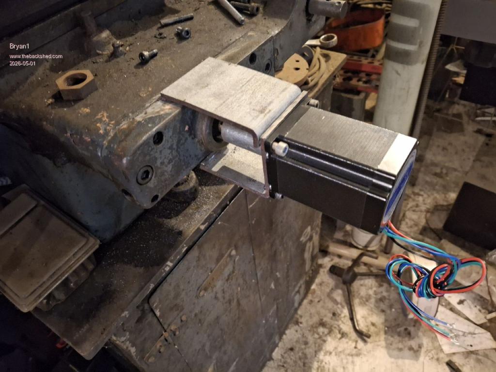 So this is the Y axis stepper mount where I have some 100mm x4mm thick square RHS to use so by using a 40mm holesaw and drilling/tapping M5 the stepper can be mounted. The lower part was made first and got the height right so the stepper does just slide in and out and with the top section for now I will bolt it in and once it's right I will put a weld across that top section to fully brace it. Still got drill the top plate and drill/tap some M6 holes to mount the plate, as the leasdscrew isn't centred on the front plate it was a bit of fun getting the height right. Now will will get this Y axis all finished now I have all the flexible couplings as with the X axis the output shaft is 5/8" so I'll machine the hard coupling to 5/8" to the X axis can be installed. Now I did have some thrust bearings here so the Y axis got a new one and I did find the X axis one was still good. The pin holding the X axis handle is pretty tight so I'm going to drill it out then I can check the shaft size and if is 1/2" that will be next axis to install. So getting there guy's and still a heap of work to go where alot of thought is needed designing these stepper mounts. Well on the bright side as Lyle is going to do his once I get mine all setup I can take of plenty of pictures so he doesn't go thru the same fun I have building the stepper mounts Regards Bryan Edit: With a bit of coaxing managed to get the handle and dial off the X axis and yes the shaft is 1/2" now I do think keeping the dial on is a good idea so I will need to make a bush as it was a press fit on the handle. Now my idea is once the bush is made use a grub screw to lock it to the 1/2" shaft then a thumb screw can lock the dial onto the bush.This will come in handy when testing the X axis and also keep the theme of the old machine. Edited 2026-05-01 13:56 by Bryan1 |
||||
| Bryan1 Guru Joined: 22/02/2006 Location: AustraliaPosts: 2155 |
Ok welded up the top brace and after cleaning up the weld, retapped the top holes as there were very close to the weld and with the hard coupling on it pushed home very easily Machined up the first flexible coupling 1/2" and re tapped the grub screw hole to 6mm and made an impression in the shaft with a 5mm drill to let the grubscrew clamp right down for the drive. 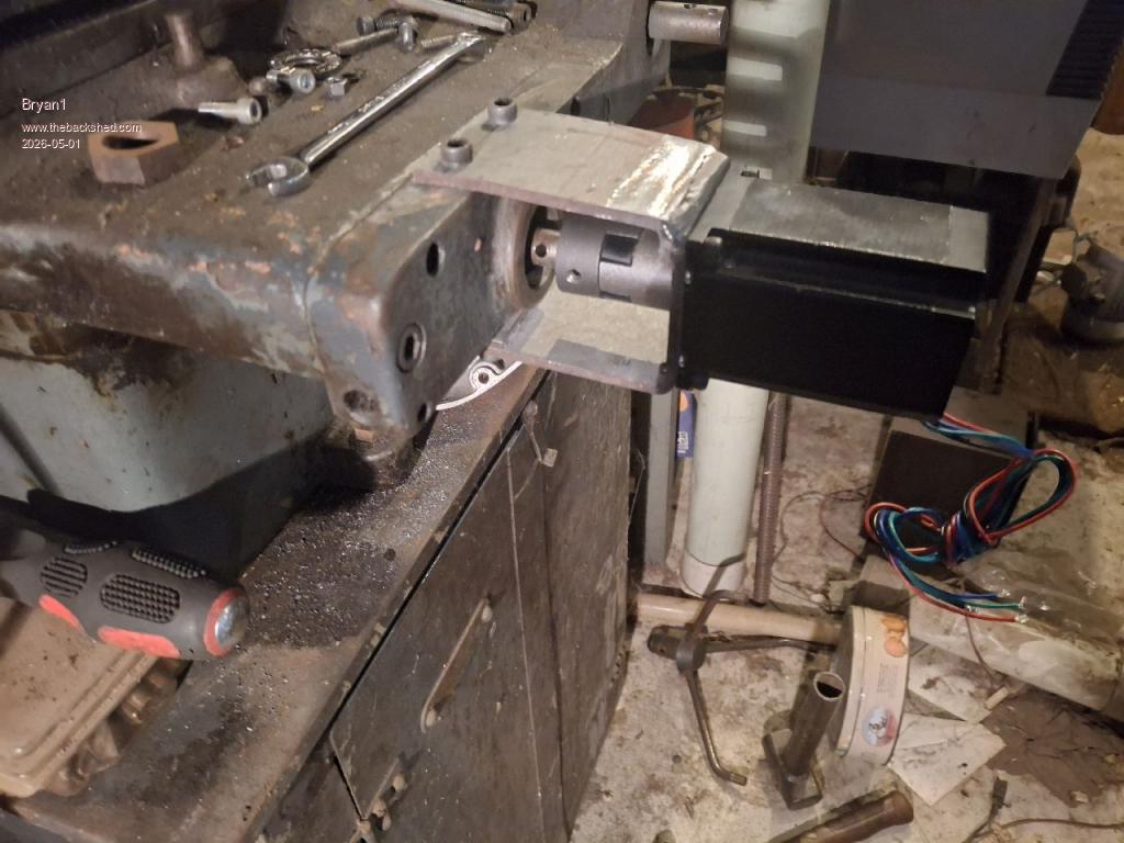 After I put the stepper on checked the alignment of the flexible coupling and it's within 0.002" so there shouldn't be any pressure on the stepper bearings.Now the fun part of designing the X axis mount 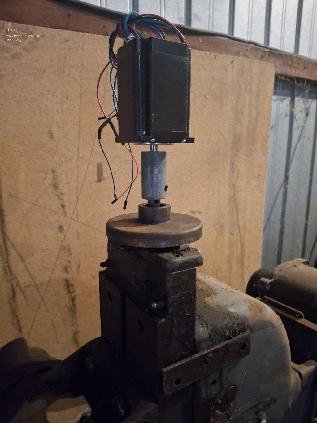 As the Y axis did take a few days to do this X axis needs a whole new train of thought and that yard arm is getting pretty close Regards Bryan |
||||
| PhenixRising Guru Joined: 07/11/2023 Location: United KingdomPosts: 2003 |
Probably already aware of this but it's also a good idea to not have the coupling fully pushed together so that any float from the screw side doesn't get transferred to the motor shaft. |
||||
| Bryan1 Guru Joined: 22/02/2006 Location: AustraliaPosts: 2155 |
The more I'm thinking about this the easier it's going to be been scratching around looking for steel to use and as I do have plenty of 50x6 angle iron trimming some down to mount on each side of the slide then weld in a plate on the top then a flat plate to mount the stepper. Also welding on some bracing so the stepper is nice and firm on the mount.Now the X axis one I do have make and bolt on a plate then workout the best way to mount the stepper which is going to take alot of thought on going the best way to make a solid mount. I am thinking of mounting the DM556's on the left side of steel bench so if they do get hot plenty of steel as a heatsink. Then after every is done just make a case with a door to enclose it all.With that relay board I showed I do think it's best job as I'm just going to use that single phase motor can be used the start switch using a M code in the code. Now as this came without the AC connections at a later stage I will put up a pic of the motor connection so I can get the wires right. Now for getting my head back around G-Code this is a great site that list every G-Code command with examples So Peter if you want to have look more G-Code options can be put in.I have been thinking alot about the coding and a touch screen I do think is the way to go then each task can have a control so a heap of Case sub's will be made where a new page on the LCD can be shown to do each task. For example: The grinding wheel will soon glaze under work so a setting will need to be made so putting the diamond sharpener on the magnetic table will have a set height that can be adjusted in a new page on the LCD where each axis can be adjusted then press on the start button and give the grinding wheel a sharpen. Now once each code is sorted for each task it could go in the library so once each variable is programmed in via the touch screen it's there for the next time. For the X Axis we only need to clear the magnetic cable with some dead time with the backlash taken into consideration which a new task of getting the backlash variable to add to each + - movement. So a sample code where we can jog the axis and once the dial indicator moves count the steps so we get the backlash variable. Ok this post is pretty long so time to save as I don't want to lose my words |
||||
| The Back Shed's forum code is written, and hosted, in Australia. | © JAQ Software 2026 |
