
|
|
Forum Index : Electronics : Builiding of a complete 6kW PV inverter with MPPT chargers
| Author | Message | ||||
| rogerdw Guru Joined: 22/10/2019 Location: AustraliaPosts: 815 |
I have the impression that there are a lot of these built and being used and I haven't heard of too many issues once people get them going ... and judging from your photos, your work is top class. Mine have only been running a couple of months but are going strong. So far a total of 2,023kWh between the four of them. My MPPT set-up looks like this: *Choke is ???uH (see below) *fets are FDH055N15A x3 *diodes STPS61150CW 150V Schottky 60A (2 x 30A) x 2 *PV open-circuit voltage, at full sun is 111V. *PV pwr 3kW x 4 * caps used, from scrapped Aerosharp Inverters 470uF and 560uF 450V I have four, each handling 3kW of panels and outputting up to 60 amps when conditions are good. I did blow up the 48-12v dc-dc converter amd optocouplers on two of them at the start ... until I worked out you have to discharge the caps before you start mucking around with the board. Whoops. And so far the diodes and mosfets have proved reliable with none having failed. For the inductors I followed Poida's example and used choke formers from wrecked Aerosharps and used 16 turns of 16mm2 on the first ... then 17, 18, 19T on the others as I improved my cramming efforts. I didn't even get around to measuring the uH ... and they can run warm (but I wouldn't say hot) ... but the fan comes on at 40C and runs down to 35C ... and the heatsinks don't get much over ambient. Even on a really hot day the fan keeps them under control. I'd put my money on the circumstances around the small batteries and the switching happening at the same time to have caused your grief. And maybe if higher rated diodes are available you could try them perhaps. Cheers, Roger |
||||
| wiseguy Guru Joined: 21/06/2018 Location: AustraliaPosts: 1017 |
Roger, the specs on the ST STPS61150CW diode are pretty good. Maybe Dex should replace his diodes with those based on your experience and if there are still issues copy your (Poidas) chokes. I like the "non repetitive" rating given for parts. I am assuming that does not mean never do it again or it will fail, cause that would mean the first experience damaged/weakened the part. I take it they mean allow sufficient time for any hot spots in the junction to dissipate before hitting it again. The Absolute maximum of 80A RMS per diode is ~ 110A peak For a 10mS sine (non repetitive) it is 500A per diode. So for just the two diodes in one pack they can take a belt of ~1000A for a few milliseconds, which is nearly double the diodes that failed. Given that Mab also recently had a similar MPPT failure - not uncommon for MPPT units (also not uncommon for Victrons with their expired warranty still in sight...) I decided to read up on what makes MPPTs fail to try to find out what part/s are getting stressed. I killed a diode and FET in my unit bench testing a while ago, so I got the sense that maybe MPPT failures might not be rare events, Edited 2024-04-30 18:01 by wiseguy If at first you dont succeed, I suggest you avoid sky diving.... Cheers Mike |
||||
| nickskethisniks Guru Joined: 17/10/2017 Location: BelgiumPosts: 428 |
The higher the input/output ratio the more stress for the diodes. I've run the mppt at 100A charging current limit for years with irfp4110/30cpq100 combo, 2 each, and forced cooling. This was only with 60-62V nominal in and 52-54V out, so high dutcycles. I did had a MOSFET blowup but I suspect actually a PCB fault because of moist and dust build up close to the gate. The board was exposed to my basement environment, allthoug not that bad, but you could see a lot of coroded spots on the PCB. The board transferred 15000kWh of energy before 1 MOSFET failed. I'm now running the same setup(silicon) with newer panels but current is devided over 3 boards now with max of 55A charging current, with 78V in and 52V-55V out. I feel I need to switch to 150V devices but the hardest stressed board did 1100kwh now. |
||||
| KeepIS Guru Joined: 13/10/2014 Location: AustraliaPosts: 1399 |
Most mppt regulators have a recommended input voltage as a ratio to output, go above that and no guarantee it won't fail under high load. I'm not near the manuals at the moment but from memory 1.5 to a max of twice the output for the input voltage. I know that's also suggested for max efficiency in some solar regulators. I've repaired a number of mppt regulators for people, and in every case, re-configuring and dropping the PV output solved the ongoing random failures, and without any loss in available current or efficiency. But that's only my experience, for what it's worth. It's all too hard. Mike. |
||||
| rogerdw Guru Joined: 22/10/2019 Location: AustraliaPosts: 815 |
I reckon someone recommended them somewhere in that epic original mppt build thread by Poida, so that's why I used them. And I didn't fancy trying to reinvent the wheel and experiment with chokes, so I just copied Poida there again ... and it's worked for me so far. I should disconnect one and see what the inductance is and what difference there is between the 16T and 19T ones. It's hard to know just how many have been built and are working away in the background. There always seemed to be people putting their hands up for boards every time there was a batch ordered. Oh okay. Perhaps I'd better tread a bit more carefully with mine. I do have a heap of spare parts and could/should build up another one as a spare perhaps. I did wonder what the limits were, so maybe I was a bit ambitious running mine 3s4p ... maybe I should have stuck to 2s6p ... but so much more wiring!!! Not going to change it though ... too much work to rewire. Haha, I thought I was game going for 60 amps. That's a serious amount of energy collected there, impressive. It's always helpful to know what causes any failures so we can implement improvements ... but even if we don't know for sure ... Poida's initial aim was for us to be able to fix them if they did blow up ... and he has definitely succeeded there. My Voc is 111v but the highest I ever recall seeing as input is 92 volts ... with a 48-60v output Any further panels will come in via ac-coupling so I can have a couple of much higher voltage strings and a lot less wiring. The 6.6kW I put up recently comes in in two strings and are way under the inverter voltage limits. Cheers, Roger |
||||
| -dex- Regular Member Joined: 11/01/2024 Location: PolandPosts: 49 |
Thank you all for your help and valuable information  I checked what is available from my nearest suppliers and I decide to try SiC B2D30065H1 diodes. Its price is only slightly higher than the standard 2x30 dual shotky. I'll use 2 of them for one MPPT. Here is datasheet BASiC-B2D30065H1_Rev_0_1.pdf |
||||
| nickskethisniks Guru Joined: 17/10/2017 Location: BelgiumPosts: 428 |
I don't recommend pushing the current at these 100A levels. It's always a better practice to split this up when possible. I'm using ETD59 cores with as much as copper windings and 100uH. At 40khz. Also something very important is to consider a shorted MOSFET as a big problem, charging current will not be interrupted when end of charge voltage limit is reached. Always build in a secondary relay or equivalent to disconnect the controllers/solar panels when this happens. |
||||
| -dex- Regular Member Joined: 11/01/2024 Location: PolandPosts: 49 |
I tested another MPPT again, with the same diodes as before (I had nothing to do, waiting for new ones  ) and with set of small batteries. Up to about 1.5 kW everything was fine, then my wife turned on the dishwasher and the total consumption was about 2.5 kW. Then MPPT went BANG BANG - it got damaged, but unlike before, it made it even worse - only the mosfet is shorted. This means full voltage from the pv panels on the bus bars - ~100V. Good thing I was nearby and managed to disconnect the batteries, because they were already starting to bubble. ) and with set of small batteries. Up to about 1.5 kW everything was fine, then my wife turned on the dishwasher and the total consumption was about 2.5 kW. Then MPPT went BANG BANG - it got damaged, but unlike before, it made it even worse - only the mosfet is shorted. This means full voltage from the pv panels on the bus bars - ~100V. Good thing I was nearby and managed to disconnect the batteries, because they were already starting to bubble.I see a pressing need for another layer of protection - against too high voltage from a shorted MPPT. Need to protect it when LifePo4 nominally ~51V receives 100V and is charged with an uncontrolled current and the voltage increases. There would have to be a circuit that measures the voltage on the bus bar and, for example, above 65V it disconnects additional the serial relay The lifepo4 battery has a BMS from JK model 200A, but it will not survive when it sees 100V DC at the input, the inverter may also be damaged. It would be best to disconnect the PV inputs, but a good gas-sheathed DC relays (4 pcs for mine) are expensive. So perhaps a good solution would be to disconnect the entire MPPT group. I just don't know what in situation where one MPPT fails, and send high voltage to rest MPPTs outputs Maybe we should also disconnect 12V from them, when one mppt fails. 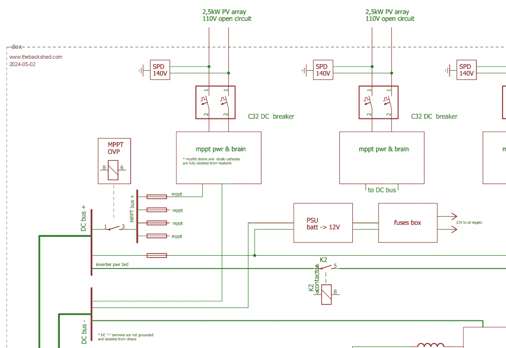 Edited 2024-05-02 18:31 by -dex- |
||||
| phil99 Guru Joined: 11/02/2018 Location: AustraliaPosts: 1813 |
If this is going to be a rare event perhaps simple crowbar protection will do. A suitably rated fuse at each MMPT output gets blown by a SCR triggered by over voltage at the output. To protect the SCR from the peak battery current a series resistor** that limits the current to 2 or 3 times the fuse rating should be in series with it. ** A suitable length of iron wire could be wound around a ceramic bar radiator element. After the fuse has blown it will be absorbing the current from the panels so it will get hot. Eg if the resistor is 0.3Ω and the panels can produce 50A it will dissipate 750W. The ceramic radiator elements are usually 1kW. |
||||
| KeepIS Guru Joined: 13/10/2014 Location: AustraliaPosts: 1399 |
Wonder if the Kilovac Automotive Relay 12-900V High Voltage DC Contactor 500+ A carry, might work, one on each mppt output. I've been using them on the inverter for a long time, have had no trouble breaking 600 A @52v many times, I know your voltage is higher, but might be worth a try as the cost had come way down from what they used to be. That with Phil's suggestion of a beefy SCR and load as worst case scenario backup. Just a thought. It's all too hard. Mike. |
||||
| -dex- Regular Member Joined: 11/01/2024 Location: PolandPosts: 49 |
KeepIS - you said earlier that you have your own lifepo4 packages and a lot of your own experience with them. Can you despair of the scenario of events when, for a battery with a nominal voltage of ~51V, we supply more than twice as much - the question is whether the voltage will immediately be at ~100VDC or it firstly will drop to the battery voltage and slowly increase? |
||||
| nickskethisniks Guru Joined: 17/10/2017 Location: BelgiumPosts: 428 |
One thing to do is to set absorb voltage very low and time short, so it's not immediately a problem as there is extra capacity to charge. I only had a series MOSFET array between solar controller and battery but then Al voltage was directly on my inverter, but it stayed open and my inverter stayed working on 80V for the afternoon...😅 That's why I keep using 100V MOSFETs. (Back then there was not yet the poida code running on the controller, just constant PV voltage regulation) Lesson learned and implemented a contactor between solar and regulators. I recently ruined one with rewiring so I want to build some MOSFET switches. Allthoug contactors are more robust but use more energy. There will be some back emk when disconnecting the panels, this will probably less when disconnecting the mppt outputs, but then you need to use output caps rated for the input voltage. |
||||
| oreo Newbie Joined: 11/12/2020 Location: CanadaPosts: 40 |
I am not sure what shipping will cost you, but these used TE Connectivity EV200AAANA relays are a good price and are good high voltage DC relays (I have gotten a couple and measured them, but have not used them for anything). EV200AAANA Battery Hookup Greg |
||||
| KeepIS Guru Joined: 13/10/2014 Location: AustraliaPosts: 1399 |
Apology for my overly long reply. All of this depends on the maximum current @ ?? voltage available from the Solar array, the size of the LifePO4 battery bank and the configuration of the bank and array. With my 12kW of solar for the LifePO4, I have more on a separate Mains feed in, there is some serious power available. If a Solar regulators shorts the Solar array voltage to the Battery, then a big LifePO4 bank with a good BMS will switch off, but as has happened before, the BMS is not designed for a sudden high voltage across the FETS at the moment of OV protection and isolation, some use a relay for isolation or have an external drive for one, much better. As you noted and found: Reports of FETS shorting and destroying the LifePO4 bank have been reported - so now you basically have NO BMS, and you have a big problem. A big battery bank capable of charging at around 500A in bulk voltage mode will, as you said, will pull the solar array down to a much lower voltage, but if you are not there, disaster is a short time away. The way mine is configured, there is never going to be enough voltage or current unless all 5 solar regulators short. I have 4 parallel banks of LiFepo4, each has a BMS, each has an isolation switch, and each bank has a low current 80A Fuse. But an 80A fuse will hold high current for X time, but you can see where most of the banks would isolate, and the rare possibility of one bank taking out a FET. However my Solar arrays have a VOC of around 90v, under any load the mppt sits at around 70V, so it's likely the 4 BMS devices will handle that. I also have each Solar regulator de-rated, there are 5 solar regulators, and all solar array outputs are fused just above the max current of each array, each Solar regulator has a current tripped isolation switch on the output, so it's pretty hard for the system to fail in that manner. There is a lot to be said for dividing everything up having the ability to isolate any part of the system that failed. Not the least for redundancy in an emergency failure situation, but also to lower the power each section has to handle, and much lower fuse ratings can be used. IMHO the Kilovac would be a really good backup fail safe. They are rated at high voltage and current on release. I bought four of the 48v to 72v coil with economizer for $38.0 each in AU about 4 month ago, I had have three 24v units from a few years back, not a single failure - and man have I abused them !!! . Edited 2024-05-03 11:48 by KeepIS It's all too hard. Mike. |
||||
| nickskethisniks Guru Joined: 17/10/2017 Location: BelgiumPosts: 428 |
If you have a big hot water storage tank, than you can use it also as a extra load. Now back to the blowing silicon, something we never did was actually calculating the minimum capacity/inductor. At least I didn't do that for the first version, I used as much as was practical. So I think I can say we all use to much capacitors, but this will give us a very long lifetime,although these are capable of providing a lot of current with low impedance. So if there is a sudden demand (inverter for instance) for current in the circuits it's possible its provided by the caps in the controller. The controller is to slow to change the duty cycle and lots of current will flow thru the MOSFET, and then thru the diode. That's why silicon is blowing, populating less capacitors could be beneficial in your case. |
||||
| KeepIS Guru Joined: 13/10/2014 Location: AustraliaPosts: 1399 |
I came to the same realization some time ago for the same reasons, I removed half of the Caps from the inverter a year ago. I've toyed with the idea of current sensing between the capacitors boards and FETs, which is not uncommon, but so far everything is running fine - I'll leave sleeping dogs lie - for now. It's all too hard. Mike. |
||||
| KeepIS Guru Joined: 13/10/2014 Location: AustraliaPosts: 1399 |
@ -dex- I somehow missed your post of the circuit layout Posted: 06:18pm 02 May 2024. The Kilovac or equivalent you show between the DC bus and MPPT bus is the way I think it should be done, everything I/we do is aimed at protecting the LiFePO4 banks, IMHO the MPPT regulators can look after themselves. You have fuses on the MPPT outputs but I have breakers, some of my MPPT controllers are Auto voltage sensing, which is a pain, they need to be isolated from the Arrays to setup correctly, and supposedly need to be powered off after updating settings - I'm guessing as a precaution to ensure the installer actually set and saved the settings correctly. You look to have everything set up correctly and in a similar fashion to mine. Yes I agree, not only is my absorb low, but my bulk charge current of a "max" 30A per bank is reasonably low and hardly ever reached, as I never discharge much below 60% SOC, my average charge is around 10A per bank and drops quickly. The max SOC I aim to reach at the end of the day is around 90%, but can be as low as 80% on overcast rainy days. You might need to top charge/balance once a year when doing this as there can be a slight memory effect, but it's completely eliminated with one top balance, do NOT confuse this with the old memory effect of LI. The bulk charge rate and max SOC you select is of course, totally dependent on the system design parameters for your installation, solar array size, battery size, and your power usage, there is "NO" one size fits all. If you are looking for long term LiFePO4 battery life - The aim should be to not have the batteries sit above 90% SOC for too long. Most recent data again supports what a lot of off grid users also found, LiFePO4 likes to be on a discharge cycle as soon as possible after the charging cycle is close to completion, and there is no need to fully charge a LiFePO4 bank every day, both of these ideas were suggested a long time ago and crapped on back then. Apology -dex- as this is partly off topic in your thread. . Edited 2024-05-06 13:10 by KeepIS It's all too hard. Mike. |
||||
| -dex- Regular Member Joined: 11/01/2024 Location: PolandPosts: 49 |
Update regarding the MPPT system - I soldered new SiC B2D30065H1 diodes (52A continous current @ Tc=135°C), two pieces per module. Now MPPT works and survived tests So far, the highest power from MPPT that I have seen is ~2kW - the pv panels did not allow more yet.As for the inductor, I personally checked it in several calculators, which suggested a certain minimum inductance value. For the capacitance value of the capacitors, I was not able to calculate it. I did what was advised here - "any reasonable capacity value will do" or use what you have on hand. My capacitors are several-year-old storage units, measured parameters in the photo. Can anyone calculate what capacity value will be safe? 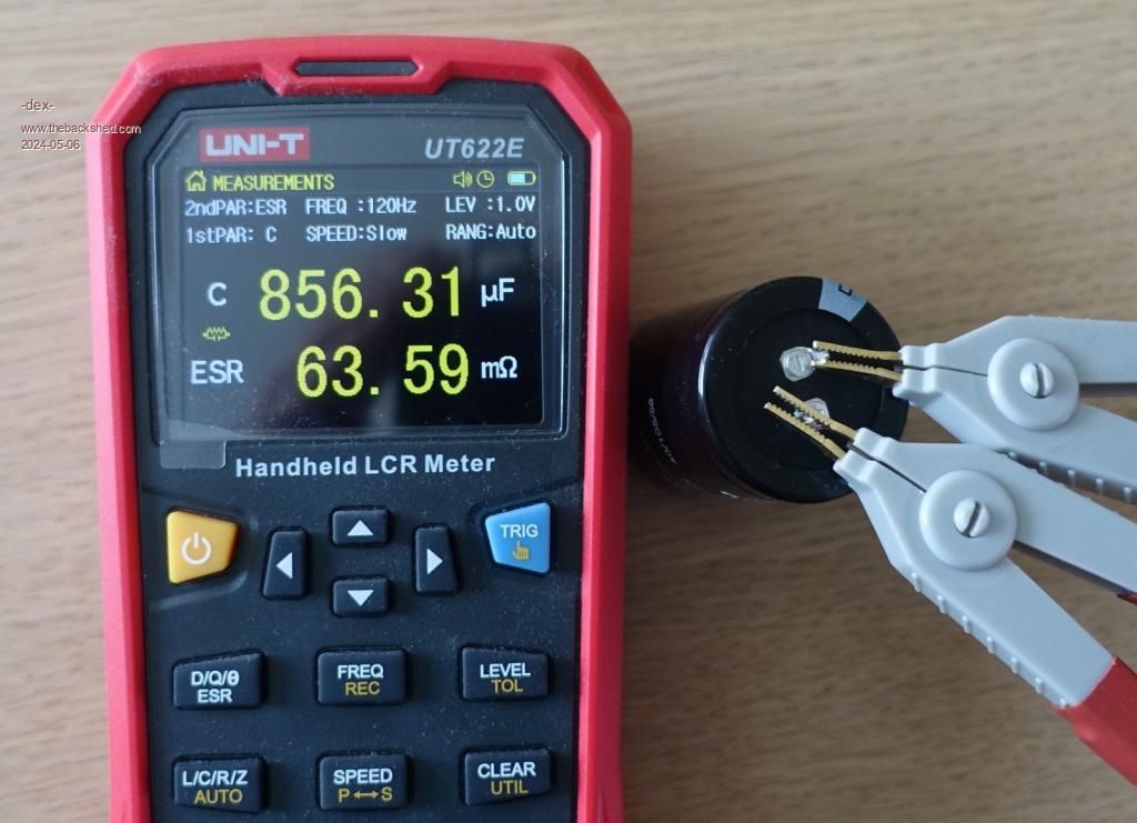 Is it possible to approach it from the other side and appropriately oversize the mosfet and diode for this event? In my mpppts all PV side & output side capacitors are 300V rated. So if one mppt has a shorted mosfet, it sends ~100V to the outputs of the other mppts. While other mpts runs, get 100V at ther outputs, they are safe or not? I also saw in your built that you used diodes in series to connect the MPPTs, in this situation should block the high voltage from reaching the other MPPTs. Back to protector & kilovac I used this kilovac in my inverter. I will use the same model in OVP protect circuit on the MPPT bus. The G version is available in digikey, 48V coil with economizer. AEV250_2.pdf |
||||
| nickskethisniks Guru Joined: 17/10/2017 Location: BelgiumPosts: 428 |
Using the best mosfets/diodes is good but not always needed. We sure need to use good quality parts, we want to (try) do better then commercial units. I use exactly the same capacitors, new old stock Yes they are safe to use. Minimum capacitance depends on the ripple voltage you want on the output: this is a good starting point: https://www.allaboutcircuits.com/technical-articles/choosing-capacitance-values-for-a-step-down-switching-regulator/ Don't expect a lot capacitance needed for a (theorethical) small ripple voltage. Other parameters will have a greater effect, for example a low esr. There are also other parameters to consider when selecting capacitors, like the ripple current they need to handle and dissipating the heat. Keeping the ripple current low and you can use smaller and so less capacitors. It's difficult to calculate "safe" values, I think your events are rather rare. You are the first I know and a lot of abuse has happened to these units. But we need to keep in mind a lot of energy is transferred, and while playing with capacitors and inductors 10folds of current/voltage can flow vs nominal values. When paralleling more controllers the "load transients" will be shared. A better battery and/or better output capacitors will also prevent such event. The higher the inductance value of the inductor the slower (di/dt) current will rise during transients and the better current is shared between mosets/diodes. Even some longer/lossier cables could help reducing peak currents. Don't take above as absolute truth, it's just a point of view, it's also late and there is a lot in to play. Edited 2024-05-07 07:34 by nickskethisniks |
||||
| -dex- Regular Member Joined: 11/01/2024 Location: PolandPosts: 49 |
I made a circuit intended to protect everything in the event of MPPT failure and full voltage from the panels. Circuit measures the voltage on the main bus, and if the voltage exceeds a set threshold for a moment, the circuit turns off the kilovac and remains in this state until it is reset. I placed an additional relay on the PCB through which I supply 12V voltage to the MPPT systems. So when the kilovac is disconnected, all MPPT circuits are turned off. I will use the second relay's pole for signaling - optical, sound, sending a notification or anything else. Circuit consumes approximately 17mA thus ~1W + kilovac consumption. I tested it and it works and latching perfectly. Treshold is in the range of ~52-65V setting by pottentiometr. The last issue is to check whether there will be no random shutdowns caused by transients and voltage changes during system operation. Now, treshold time is approximately 0.5s. Adding a larger delay of several seconds to the system is a bit troublesome ovp_mppt.pdf 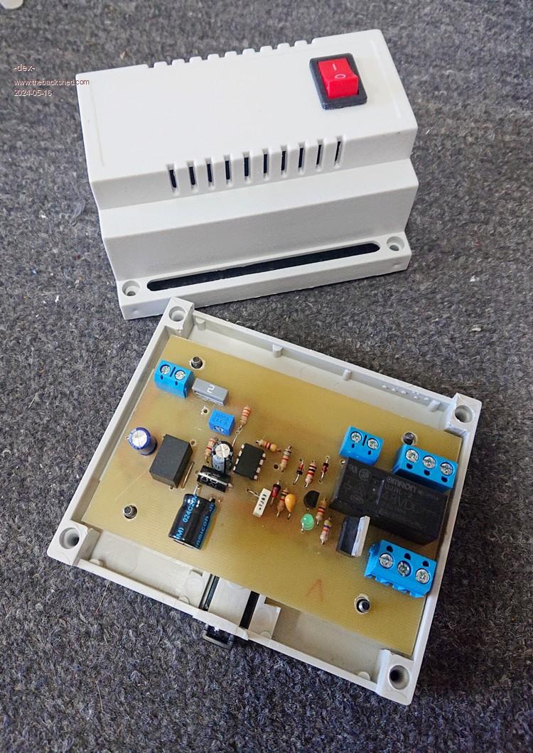 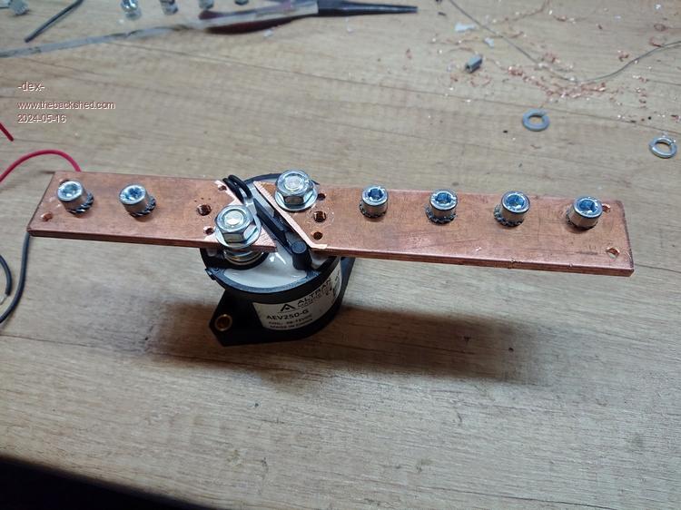 Edited 2024-05-16 23:17 by -dex- |
||||
